Dodge Durango (HB). Manual - part 772
P0111-INTAKE AIR TEMPERATURE SENSOR RATIONALITY (CONTINUED)
4.
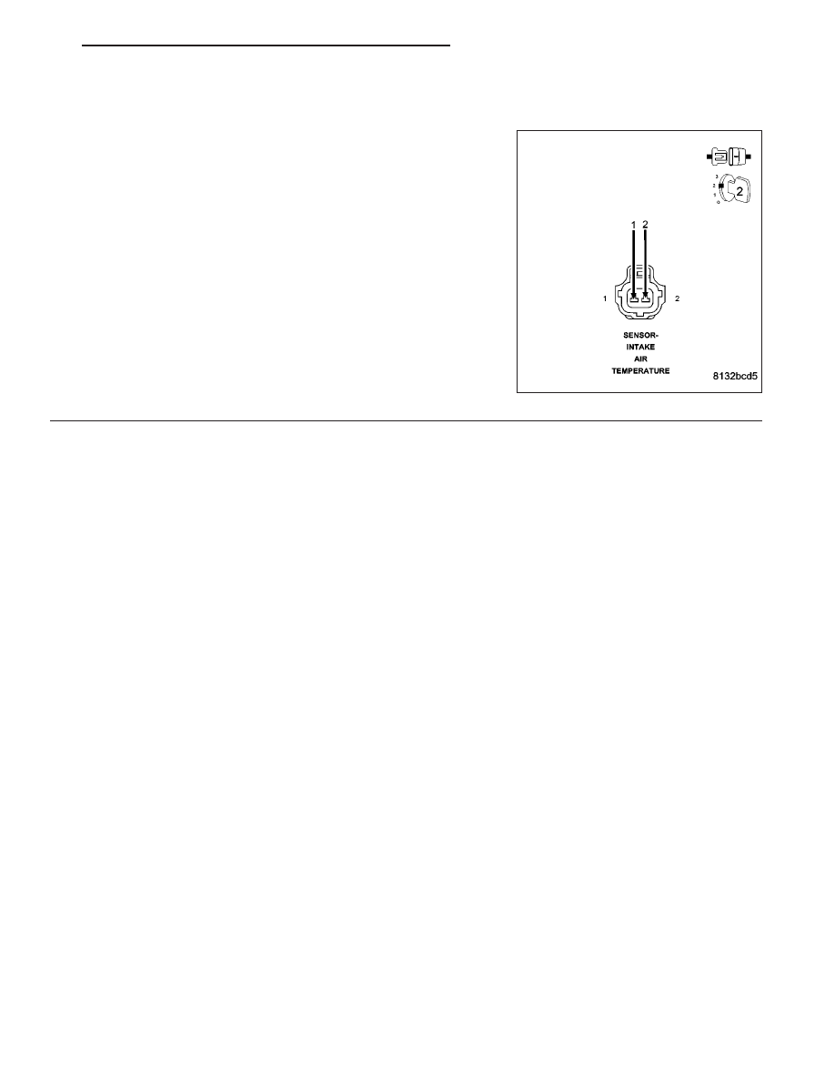
IAT SENSOR
Connect a jumper wire between the (K21) IAT Signal circuit and the
(K900) Sensor ground circuit in the IAT Sensor harness connector.
With a scan tool, read the IAT voltage.
Is the voltage below 1.0 volt with the jumper wire installed?
Yes
>> Replace the IAT Sensor.
Perform the POWERTRAIN VERIFICATION TEST. (Refer
to 9 - ENGINE - STANDARD PROCEDURE)
No
>> Go To 5
NOTE: Remove the jumper wire before continuing.
HB
ENGINE ELECTRICAL DIAGNOSTICS
9 - 87