Dodge Durango (HB). Manual - part 616


  Index      Dodge     Dodge Durango (HB) - service repair manual 2005 year


Search            


Content   ..  614  615  616  617   ..


Dodge Durango (HB). Manual - part 616


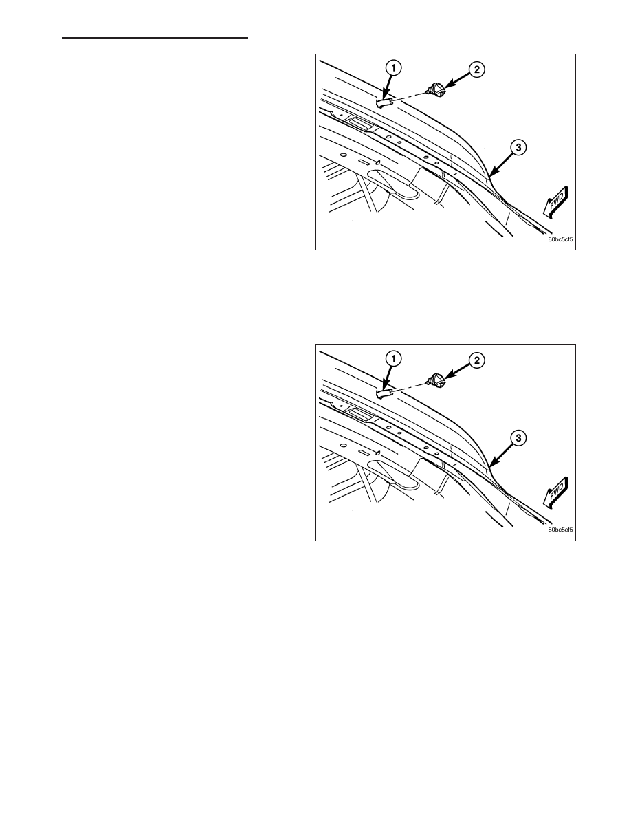
1. Using a trim stick or another suitable wide flat-

bladed tool, gently pry at the bottom of the rear
washer nozzle (2) to release the latch feature that
secures it in the mounting hole of the liftgate outer
panel (3).

2. Pull the rear washer nozzle out from the liftgate

outer panel far enough to access the washer hose
(1).

3. Disconnect the hose from the barbed nipple on the

back of the nozzle.

4. Discard the nozzle.

INSTALLATION

NOTE: The rear washer nozzle latch feature is a one time component, and will be damaged if the nozzle is
removed from its mounting hole for service. If removed from its mounting hole for any reason, the rear
washer nozzle must be replaced with a new unit.

1. Position the new rear washer nozzle (2) to the

mounting hole in the liftgate outer panel (3). Be
certain that the rubber gasket is in position on the
back of the nozzle.

2. Reconnect the washer hose (1) to the barbed nip-

ple on the back of the nozzle.

3. Push the hose and nozzle nipple into the mounting

hole in the liftgate outer panel and engage the tab
located above the nipple with the upper edge of the
hole.

4. Using hand pressure, push firmly and evenly on

the lower edge of the nozzle until it snaps into
place.

HB

REAR WIPERS/WASHERS - SERVICE INFORMATION

8R - 87

RELAY-WIPER-REAR

DESCRIPTION

The rear wiper relay is a conventional International
Standards Organization (ISO) micro relay. Relays con-
forming to the ISO specifications have common phys-
ical dimensions, current capacities, terminal patterns,
and terminal functions. This relay is contained within a
small, rectangular, molded plastic housing and is con-
nected to all of the required inputs and outputs
through five integral male spade-type terminals that
extend from the relay base plate.

The rear wiper relay is located in the Power Distribu-
tion Center (PDC) in the engine compartment near the
battery. Refer to the layout label on the underside of
the PDC cover for specific relay cavity assignment
information. The rear wiper relay cannot be adjusted
or repaired and, if faulty or damaged, the unit must be
replaced.

OPERATION

The rear wiper relay is an electromechanical switch that uses a low current input from the Front Control Module
(FCM) to control a high current output to the rear wiper motor. The movable common feed contact point is held
against the fixed normally closed contact point by spring pressure. When the relay coil is energized, an electromag-
netic field is produced by the coil windings. This electromagnetic field draws the movable relay contact point away
from the fixed normally closed contact point, and holds it against the fixed normally open contact point. When the
relay coil is de-energized, spring pressure returns the movable contact point back against the fixed normally closed
contact point. A resistor is connected in parallel with the relay coil in the relay, and helps to dissipate voltage spikes
and electromagnetic interference that can be generated as the electromagnetic field of the relay coil collapses.

The rear wiper relay terminals are connected to the vehicle electrical system through a connector receptacle in the
Power Distribution Center (PDC). The inputs and outputs of the rear wiper relay include:

Common Feed Terminal - The common feed terminal (30) is connected to the rear wiper motor through the
rear wiper motor control circuit. When the rear wiper relay is de-energized, the common feed terminal is con-
nected to ground. When the rear wiper relay is energized, the common feed terminal of the relay is connected
to battery current from a fuse in the Power Distribution Center (PDC) through a fused B(+) circuit.

Coil Ground Terminal - The coil ground terminal (85) is connected to the relay control output of the FCM
through the rear wiper relay control circuit. The FCM controls the ground path for this circuit internally to ener-
gize or de-energize the rear wiper relay based upon its programming, rear wiper and washer request mes-
sages received from the ElectroMechanical Instrument Cluster (EMIC) over the Controller Area Network (CAN)
data bus, and a hard wired input from the rear wiper motor park switch.

Coil Battery Terminal - The coil battery terminal (86) is connected to battery current from a fuse in the PDC
through a fused B(+) circuit at all times.

Normally Open Terminal - The normally open terminal (87) is connected to battery current from a fuse in the
PDC through a fused B(+) circuit at all times.

Normally Closed Terminal - The normally closed terminal (87A) is connected to ground at all times.

The rear wiper relay may be diagnosed using conventional diagnostic tools and methods. Refer to the appropriate
wiring information. However, conventional diagnostic methods may not prove conclusive in the diagnosis of the
FCM, the EMIC, the CAN data bus or the electronic message inputs or outputs that control the operation of the rear
wiper relay. The most reliable, efficient, and accurate means to diagnose the rear wiper relay, the FCM, the EMIC,
the CAN data bus and the electronic message inputs and outputs related to the rear wiper relay operation requires
the use of a diagnostic scan tool. Refer to the appropriate diagnostic information.

8R - 88

REAR WIPERS/WASHERS - SERVICE INFORMATION

HB

NAVIGATION/TELECOMMUNICATION

TABLE OF CONTENTS

page

page

NAVIGATION/TELECOMMUNICATION -

SERVICE INFORMATION . . . . . . . . . . . . . . . . . . . 1

NAVIGATION/TELECOMMUNICATION -

ELECTRICAL DIAGNOSTICS. . . . . . . . . . . . . . . . . 3

NAVIGATION/TELECOMMUNICATION - SERVICE

INFORMATION

TABLE OF CONTENTS

page

page

NAVIGATION/TELECOMMUNICATION -

SERVICE INFORMATION
DESCRIPTION

. . . . . . . . . . . . . . . . . . . . . . . . . . 1

OPERATION

. . . . . . . . . . . . . . . . . . . . . . . . . . . . 2

MODULE-HANDS FREE

REMOVAL

. . . . . . . . . . . . . . . . . . . . . . . . . . . . . . 2

INSTALLATION

. . . . . . . . . . . . . . . . . . . . . . . . . . 2

NAVIGATION/TELECOMMUNICATION - SERVICE INFORMATION

DESCRIPTION

TELECOMMUNICATIONS

The hands-free cellular system uses Bluetooth™ technology to provide wireless communication between the oper-
ator’s compatible cellular telephone and the vehicle’s on-board receiver.

The system uses voice recognition technology to control operation. The incoming voice is broadcast through the
vehicle’s radio speakers, automatically overriding any other audio signals on the front speakers when the hands-free
system is in use. A microphone in the rear view mirror picks up vehicle occupant’s voices. If a call is in progress
when the ignition is switched off, the hands-free system will continue to operate for up to 45 seconds as part of the
Accessory Relay Delay function. Thereafter, the call can continue on the hand-held telephone.

The center console front storage compartment includes a cellular telephone holder, but the system will communicate
with a telephone that is anywhere within the vehicle. However, covering the hand held phone or the hands-free
phone module with a metal object may block the signal. The system will recognize up to seven telephones, each of
which is given a spoken identification by the user during the setup process. The system includes Spanish and
French voice recognition in addition to English.

Two buttons on the rearview mirror, identified with ISO icons, control the system: A

9

phone

9

button turns the system

on and off; a

9

voice recognition

9

(or voice command) button prompts the hands-free system to listen for a voice

command.

HB

NAVIGATION/TELECOMMUNICATION

8T - 1

OPERATION

TELECOMMUNICATION

Two buttons on the rearview mirror, identified with ISO icons, control the system: A

9

phone

9

button turns the system

on and off; a

9

voice recognition

9

(or voice command) button prompts the hands-free system to listen for a voice

command. The system includes the following features:

Phonebook - Stores telephone numbers for later recall by name or other verbal identification, called a voice
tag, and memory location.

Four memory locations - Home, Work, Cellular and Pager. A maximum of 32 unique names or voice tags may
be stored at the same time, with a different number in each of the four memory locations.

Voice tag dialing - Dials the number associated with a voice tag and memory location.

Digit dialing - Dials the telephone number by recognizing the names of the digits as they are spoken.

Receiving calls - A voice prompt notifies the user of an incoming call. A voice response accepts or rejects the
call without manual intervention.

Privacy Mode - Switches the call to the handheld telephone and the hands-free system and back again using

the “voice recognition” (or “voice command”) button and a voice command, if desired.

MODULE-HANDS FREE

REMOVAL

1. Disconnect and isolate the battery negative cable.

2. Remove the instrument panel end cap (3).

3. Remove the mounting fasteners.

4. Disconnect the electrical harness connector and

remove the module (4).

INSTALLATION

1. Connect electrical harness connector and position module.

2. Install mounting fasteners.

3. Install instrument panel end cap.

4. Connect battery negative cable.

8T - 2

NAVIGATION/TELECOMMUNICATION - SERVICE INFORMATION

HB


Content   ..  614  615  616  617   ..