Dodge Durango (HB). Manual - part 614


  Index      Dodge     Dodge Durango (HB) - service repair manual 2005 year


Search            


Content   ..  612  613  614  615   ..


Dodge Durango (HB). Manual - part 614


REMOVAL

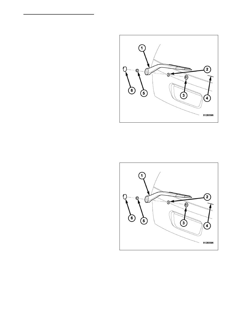
1. Insert the tip of a small screwdriver into the notch

on the large end of the rear wiper arm (1) and
carefully pry the plastic cap (6) until it unsnaps
from the mounting hole on the pivot end of the
arm.

2. Remove the nut (5) that secures the arm to the

rear wiper motor output shaft (3).

CAUTION: The use of a battery terminal puller
when removing the rear wiper arm is NOT recom-
mended as this may damage the rear wiper arm.

3. Use a slight rocking action to remove the rear

wiper arm from the output shaft.

INSTALLATION

NOTE: Be certain that the rear wiper motor is in the park position before attempting to install the wiper arm.
Turn the ignition switch to the On position and move the rear wiper switch to its Off position. If the wiper
motor output shaft moves, wait until it stops moving, then turn the ignition switch back to the Off position.
The wiper motor is now in its park position.

1. The rear wiper arm (1) must be indexed to the

motor output shaft (3) with the rear wiper motor in
the park position to be properly installed. Position
the rear wiper arm pivot end onto the motor output
shaft so that the wiper blade is aligned with the
alignment mark (4) located in the upper margin of
the lower liftgate glass blackout area on the lower
right corner of the liftgate glass.

2. With the wiper arm properly indexed, push the

tapered mounting hole on the pivot end of the
wiper arm down over the output shaft.

3. Install and tighten the nut (5) that secures the arm

to the shaft. Tighten the nut to 12 N·m (9 ft. lbs.).

4. Wet the liftgate glass, then operate the rear wiper.

Turn the rear wiper switch to the Off position, then
check for the correct wiper arm position and adjust
as required.

5. Insert the tab of the plastic cap (6) into the mount-

ing hole on the side opposite the notch and press firmly on the notched side of the cap until it snaps into place.

HB

REAR WIPERS/WASHERS - SERVICE INFORMATION

8R - 79

BLADE-LIFTGATE WIPER

DESCRIPTION

The rear wiper blade is secured by two integral latch-
ing pivot pins (1) to a receptacle in the small end at
the tip of the rear wiper arm, and rests near the base
of the liftgate glass when the wiper is not in operation.
The rear wiper blade consists of the following compo-
nents:

Superstructure (4) - The superstructure includes
a molded black plastic bridge and plastic links
with claw formations that grip the wiper blade
element. Also included in this unit are the two
latching pivot pins that secure the superstructure
to the wiper arm.

Element (2) - The wiper element or squeegee is
the resilient rubber member of the wiper blade
that contacts the glass.

Flexor (3) - The flexor is a rigid metal compo-
nent running along the length of each side of the
wiper element where it is gripped by the claws of
the superstructure.

The rear wiper blade is 30.10 centimeters (11.85 inches) long with a replaceable element (squeegee). The wiper
blade superstructure cannot be adjusted or repaired. If faulty, worn, or damaged the entire wiper blade unit must be
replaced.

OPERATION

The rear wiper blade is moved back and forth across the liftgate glass by the wiper arm when the rear wiper system
is in operation. The wiper blade superstructure is the flexible frame that grips the wiper blade element and evenly
distributes the force of the spring-loaded wiper arm along the length of the element. The combination of the wiper
arm force and the flexibility of the superstructure makes the element conform to and maintain proper contact with
the glass, even as the blade is moved over the varied curvature found across the glass surface.

The wiper element flexor provides the claws of the blade superstructure with a rigid, yet flexible component on the
element which can be gripped. The rubber element is designed to be stiff enough to maintain an even cleaning
edge as it is drawn across the glass, but resilient enough to conform to the glass surface and flip from one cleaning
edge to the other each time the wiper blade changes directions.

8R - 80

REAR WIPERS/WASHERS - SERVICE INFORMATION

HB

STANDARD PROCEDURE

REAR WIPER ELEMENT REPLACEMENT

1. Remove the rear wiper blade (3) from the wiper

arm. (Refer to 8 - ELECTRICAL/REAR WIPERS/
WASHERS/REAR WIPER BLADE - REMOVAL).

2. Grasp one of the wiper blade links (4) firmly with

one hand, and grasp the wiper element (1) and
flexor (2) midway between the two sets of claws (5)
for that link with the other hand.

3. Pull the element and flexor away from the link until

they flex enough to disengage them from the end
pair of claws.

4. Slide the element and flexor toward the loose end

to disengage them from the remaining sets of
claws.

5. Reverse this process to install a new element and

flexors into the wiper blade.

6. Reinstall the wiper blade into the wiper arm. (Refer

to 8 - ELECTRICAL/REAR WIPERS/WASHERS/
REAR WIPER BLADE - INSTALLATION).

REMOVAL

1. Lift the rear wiper arm (3) to raise the wiper blade

(1) and element off of the liftgate glass.

2. To remove the wiper blade from the wiper arm,

squeeze the two latch release tabs (2) together
while pulling the blade straight out from the recep-
tacle in the end of the arm.

CAUTION: Do not allow the wiper arm to spring
back against the glass without the wiper blade in
place or the glass and/or the wiper arm may be
damaged.

3. Gently lower the tip of the wiper arm onto the

glass.

HB

REAR WIPERS/WASHERS - SERVICE INFORMATION

8R - 81

INSTALLATION

1. Lift the rear wiper arm (3) off of the liftgate glass.

2. Position the rear wiper blade (1) with the latching

pivot pins aligned with the receptacle on the tip of
the arm.

3. Slide the wiper blade pivot pins into the receptacle

until they snap into place.

4. Lower the wiper blade onto the glass.

HOSE-LIFTGATE WASHER

DESCRIPTION

The rear washer plumbing consists of a small diame-
ter rubber hose that is routed along with the front
washer hose from the washer reservoir under the left
front fender ahead of the left front wheel to the engine
compartment. Both hoses are attached to their respec-
tive front or rear outlet nipple of the washer pump/mo-
tor unit near the bottom of the reservoir. The hoses
are then secured by retainers to the back of the con-
denser shroud and the underside of the Power Distri-
bution Center (PDC) bracket above the wheel house
splash shield before entering the left side of the
engine compartment behind the PDC.

In the engine compartment, both hoses are secured
by a retainer near the dash panel to the side support
member for the left front fender. The two hoses are
routed separately from this point. The front hose is
routed up toward the hood, while the rear hose (2) is
routed through a grommet and a hole in the dash
panel (3) into the passenger compartment. The hose
is then routed below the instrument panel to the left
cowl side inner panel and up the left inner A-pillar (4). Midway up the A-pillar the hose is connected with a molded
plastic in-line fitting to the headliner hose (1).

8R - 82

REAR WIPERS/WASHERS - SERVICE INFORMATION

HB


Content   ..  612  613  614  615   ..