Dodge Durango (HB). Manual - part 602


  Index      Dodge     Dodge Durango (HB) - service repair manual 2005 year


Search            


Content   ..  600  601  602  603   ..


Dodge Durango (HB). Manual - part 602


B231F-FRONT/REAR WASHER MOTOR CONTROL CIRCUIT LOW (CONTINUED)

3.

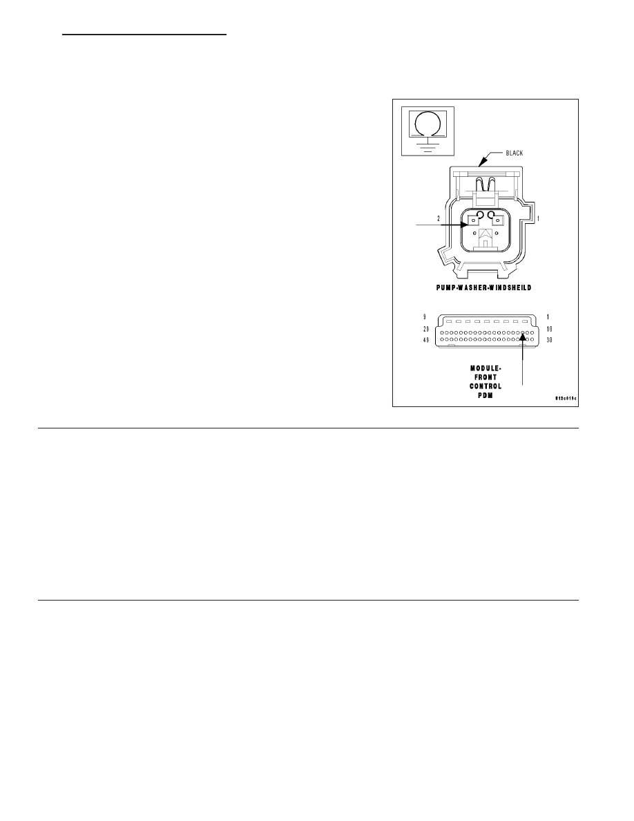
WASHER PUMP MOTOR CONTROL CIRCUIT

Turn the ignition off.

Disconnect the Washer Pump Motor harness connector.

Disconnect the FCM C3 harness connector.

Measure the resistance between ground and the (W10) Washer Pump
Motor Control circuit in the.

Is the resistance below 5.0 ohms?

Yes

>> Repair the Washer Pump Motor Control circuit.

Perform the BODY VERIFICATION TEST — VER 1.

No

>> Go To 4

4.

FRONT CONTROL MODULE

Turn the ignition off.

Disconnect the FCM from the PDC.

Measure the resistance between ground and the (W10) Washer Pump Motor Control circuit.

Is the resistance below 5.0 ohms?

Yes

>> Replace the Power Distribution Center in accordance with the service information.

Perform the BODY VERIFICATION TEST — VER 1.

No

>> Replace the Front Control Module in accordance with the service information.

Perform the BODY VERIFICATION TEST — VER 1.

HB

FRONT WIPERS/WASHERS - ELECTRICAL DIAGNOSTICS

8R - 31

SCHEMATICS AND DIAGRAMS

FRONT/REAR

WIPERS

W

ASHERS

8R - 32

FRONT WIPERS/WASHERS - ELECTRICAL DIAGNOSTICS

HB

FRONT WIPERS/WASHERS - SERVICE INFORMATION

TABLE OF CONTENTS

page

page

FRONT WIPERS/WASHERS - SERVICE

INFORMATION
DESCRIPTION

. . . . . . . . . . . . . . . . . . . . . . . . . 34

OPERATION

. . . . . . . . . . . . . . . . . . . . . . . . . . . 35

DIAGNOSIS AND TESTING

FRONT WIPER & WASHER SYSTEM

. . . . . . 37

CLEANING - FRONT WIPER & WASHER

SYSTEM

. . . . . . . . . . . . . . . . . . . . . . . . . . . . 38

INSPECTION - FRONT WIPER & WASHER

SYSTEM

. . . . . . . . . . . . . . . . . . . . . . . . . . . . 39

ARM-WINDSHIELD WIPER

DESCRIPTION

. . . . . . . . . . . . . . . . . . . . . . . . . 40

OPERATION

. . . . . . . . . . . . . . . . . . . . . . . . . . . 40

REMOVAL

. . . . . . . . . . . . . . . . . . . . . . . . . . . . . 41

INSTALLATION

. . . . . . . . . . . . . . . . . . . . . . . . . 41

BLADE-WINDSHIELD WIPER

DESCRIPTION

. . . . . . . . . . . . . . . . . . . . . . . . . 42

OPERATION

. . . . . . . . . . . . . . . . . . . . . . . . . . . 42

REMOVAL

. . . . . . . . . . . . . . . . . . . . . . . . . . . . . 43

INSTALLATION

. . . . . . . . . . . . . . . . . . . . . . . . . 43

HOSE-WINDSHIELD WASHER

DESCRIPTION

. . . . . . . . . . . . . . . . . . . . . . . . . 44

OPERATION

. . . . . . . . . . . . . . . . . . . . . . . . . . . 44

MODULE-WINDSHIELD WIPER

DESCRIPTION

. . . . . . . . . . . . . . . . . . . . . . . . . 45

OPERATION

. . . . . . . . . . . . . . . . . . . . . . . . . . . 46

REMOVAL

. . . . . . . . . . . . . . . . . . . . . . . . . . . . . 46

INSTALLATION

. . . . . . . . . . . . . . . . . . . . . . . . . 47

MOTOR-WINDSHIELD WIPER

REMOVAL

. . . . . . . . . . . . . . . . . . . . . . . . . . . . . 47

INSTALLATION

. . . . . . . . . . . . . . . . . . . . . . . . . 48

NOZZLE-WINDSHIELD WASHER

DESCRIPTION

. . . . . . . . . . . . . . . . . . . . . . . . . 49

OPERATION

. . . . . . . . . . . . . . . . . . . . . . . . . . . 49

REMOVAL

. . . . . . . . . . . . . . . . . . . . . . . . . . . . . 50

INSTALLATION

. . . . . . . . . . . . . . . . . . . . . . . . . 50

PUMP-WASHER

DESCRIPTION

. . . . . . . . . . . . . . . . . . . . . . . . . 51

OPERATION

. . . . . . . . . . . . . . . . . . . . . . . . . . . 51

REMOVAL

. . . . . . . . . . . . . . . . . . . . . . . . . . . . . 52

INSTALLATION

. . . . . . . . . . . . . . . . . . . . . . . . . 53

RELAY-WIPER HIGH/LOW

DESCRIPTION

. . . . . . . . . . . . . . . . . . . . . . . . . 53

OPERATION

. . . . . . . . . . . . . . . . . . . . . . . . . . . 53

RELAY-WIPER ON/OFF

DESCRIPTION

. . . . . . . . . . . . . . . . . . . . . . . . . 54

OPERATION

. . . . . . . . . . . . . . . . . . . . . . . . . . . 54

RESERVOIR-WASHER

DESCRIPTION

. . . . . . . . . . . . . . . . . . . . . . . . . 55

OPERATION

. . . . . . . . . . . . . . . . . . . . . . . . . . . 55

SENSOR-WASHER FLUID LEVEL

DESCRIPTION

. . . . . . . . . . . . . . . . . . . . . . . . . 56

OPERATION

. . . . . . . . . . . . . . . . . . . . . . . . . . . 56

REMOVAL

. . . . . . . . . . . . . . . . . . . . . . . . . . . . . 56

INSTALLATION

. . . . . . . . . . . . . . . . . . . . . . . . . 57

HB

FRONT WIPERS/WASHERS - SERVICE INFORMATION

8R - 33

FRONT WIPERS/WASHERS - SERVICE INFORMATION

DESCRIPTION

An electrically operated intermittent front wiper and washer system is standard factory-installed safety equipment on
this model. The wiper and washer system includes the following major components, which are described in further
detail elsewhere in this service information:

Front Control Module - The Front Control Module (FCM) is integral to the Integrated Power Module (IPM).
The FCM/IPM is located in the engine compartment, near the battery and the Power Distribution Center (PDC).
(Refer to 8 - ELECTRICAL/POWER DISTRIBUTION - DESCRIPTION).

Front Washer Nozzle (2) - Two fluidic washer nozzles with integral check valves are secured by latch features
to dedicated openings in the hood panel near the base of the windshield.

Front Washer Plumbing - The plumbing for the washer system consists of rubber hoses and molded plastic
fittings. The plumbing is routed along the underside of the Power Distribution Center (PDC) bracket to the
engine compartment from the washer reservoir. The front washer hose is routed across the underside of the
hood panel to the washer nozzles.

Front Wiper Arm - The two wiper arms are secured with nuts to the threaded ends of the two wiper pivot
shafts, which extend through the cowl plenum cover/grille panel located near the base of the windshield. The
right arm is articulated by a unique linkage arrangement to increase the wiped area of the windshield glass.

Front Wiper Blade - The two unequal length wiper blades are secured to the two wiper arms with an integral
latch, and are parked on the glass near the bottom of the windshield when the wiper system is not in opera-
tion.

Front Wiper Module (3) - The wiper pivot shafts are the only visible components of the front wiper module.
The remainder of the module is concealed within the engine compartment beneath the cowl plenum cover/grille
panel. The wiper module includes a cast aluminum wiper module bracket, four rubber-isolated wiper module
mounts, the wiper motor, the wiper motor crank arm, the two wiper drive links, the two powered wiper pivots,
and a static pivot point that is located outboard of the right pivot for the articulating link of the right wiper arm.

Instrument Cluster - The ElectroMechanical Instrument Cluster (EMIC) is also known as the Cab Control
Node (CCN) in this vehicle. The EMIC/CCN is located in the instrument panel above the steering column
opening, directly in front of the driver. (Refer to 8 - ELECTRICAL/INSTRUMENT CLUSTER - DESCRIPTION).

Multi-Function Switch (4) - The multi-function switch is located on the top of the steering column, just below
the steering wheel. A control stalk that extends from the left side of the switch has a control knob on the end

8R - 34

FRONT WIPERS/WASHERS - SERVICE INFORMATION

HB


Content   ..  600  601  602  603   ..