Dodge Durango (HB). Manual - part 590


  Index      Dodge     Dodge Durango (HB) - service repair manual 2005 year


Search            


Content   ..  588  589  590  591   ..


Dodge Durango (HB). Manual - part 590


U0019–CAN B BUS (CONTINUED)

3.

(D55) CAN B BUS (+) CIRCUIT OPEN

Turn the ignition off.

Disconnect the negative battery cable.

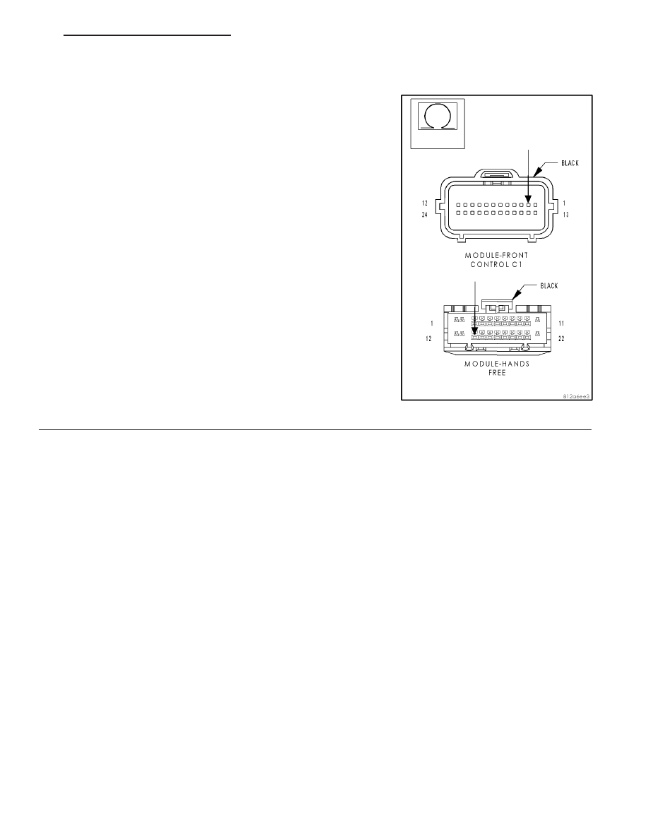
Disconnect the Hands Free Module connector.

Disconnect the Front Control Module C1 connector.

Measure the resistance of the (D55) CAN B Bus (+) circuit between
the Front Control Module C1 connector and the Hands Free Module
connector.

Is the resistance below 2.0 ohms?

Yes

>> Go To 4

No

>> Repair the (D55) CAN B Bus (+) circuit for an open.

Perform BODY VERIFICATION TEST - VER 1.

HB

VEHICLE THEFT SECURITY - ELECTRICAL DIAGNOSTICS

8Q - 79

U0019–CAN B BUS (CONTINUED)

4.

(D54) CAN B BUS (–) CIRCUIT OPEN

Measure the resistance of the (D54) CAN B Bus (–) circuit between
the Front Control Module C1 connector and the Hands Free Module
connector.

Is the resistance below 2.0 ohms?

Yes

>> Replace the Hands Free Module in accordance with the

service information.

Perform BODY VERIFICATION TEST - VER 1.

No

>> Repair the (D54) CAN B Bus (–) circuit for an open.

Perform BODY VERIFICATION TEST - VER 1.

8Q - 80

VEHICLE THEFT SECURITY - ELECTRICAL DIAGNOSTICS

HB

U0141-LOST COMMUNICATION WITH FRONT CONTROL MODULE

For a complete wiring diagram Refer to Section 8W.

(Refer to 8 - ELECTRICAL/ELECTRONIC CONTROL MODULES - DIAGNOSIS AND TESTING) for the diagnostic
test procedure.

U0146-LOST COMMUNICATION WITH CENTRAL GATEWAY

For a complete wiring diagram Refer to Section 8W.

(Refer to 8 - ELECTRICAL/ELECTRONIC CONTROL MODULES - DIAGNOSIS AND TESTING) and perform the
U0141-Lost Communication With Front Control Module test for the diagnostic test procedure.

U0155-LOST COMMUNICATION WITH CLUSTER/CCN

For a complete wiring diagram Refer to Section 8W.

(Refer to 8 - ELECTRICAL/ELECTRONIC CONTROL MODULES - DIAGNOSIS AND TESTING) for the diagnostic
test procedure.

HB

VEHICLE THEFT SECURITY - ELECTRICAL DIAGNOSTICS

8Q - 81

SKREEM VERIFICATION

For a complete wiring diagram Refer to Section 8W.

Diagnostic Test

1.

SKREEM VERIFICATION

NOTE: When entering the PIN, care should be taken because the SKREEM will only allow 3 consecutive
attempts to enter the correct PIN. If 3 consecutive incorrect PIN’s are entered the SKREEM will Lock Out the
scan tool. To exit Lock Mode, the ignition key must remain the Run position for I hour. All accessories must
be off. A battery charger connected to the battery during this time period is recommended.

1. Reconnect the previously disconnected components and connectors.

2. Obtain the vehicle’s unique Personal Identification Number (PIN) assigned to it’s original SKREEM. This num-
ber can be obtained from the vehicle invoice or from the DaimlerChrysler Customer Center (Phone 1-800-992-
1997).

3. With the scan tool, select Miscellaneous Functions, WCM/Wireless Control Module. Then select the desired
procedure and follow the display on the scan tool.

4. If the SKREEM was replaced, ensure all the customer’s key have been programmed to the new module.

5. With the scan tool, ease all DTCs. Perform 5 ignition key cycles, leaving the key on for at least 90 seconds
per cycle.

6. With the scan tool, read SKREEM DTC(s).

Are there any SKREEM DTC(s) present?

Yes

>> Repair not complete, refer to the appropriate symptom.

No

>> Repair is complete.

8Q - 82

VEHICLE THEFT SECURITY - ELECTRICAL DIAGNOSTICS

HB


Content   ..  588  589  590  591   ..