Dodge Durango (HB). Manual - part 562


  Index      Dodge     Dodge Durango (HB) - service repair manual 2005 year


Search            


Content   ..  560  561  562  563   ..


Dodge Durango (HB). Manual - part 562


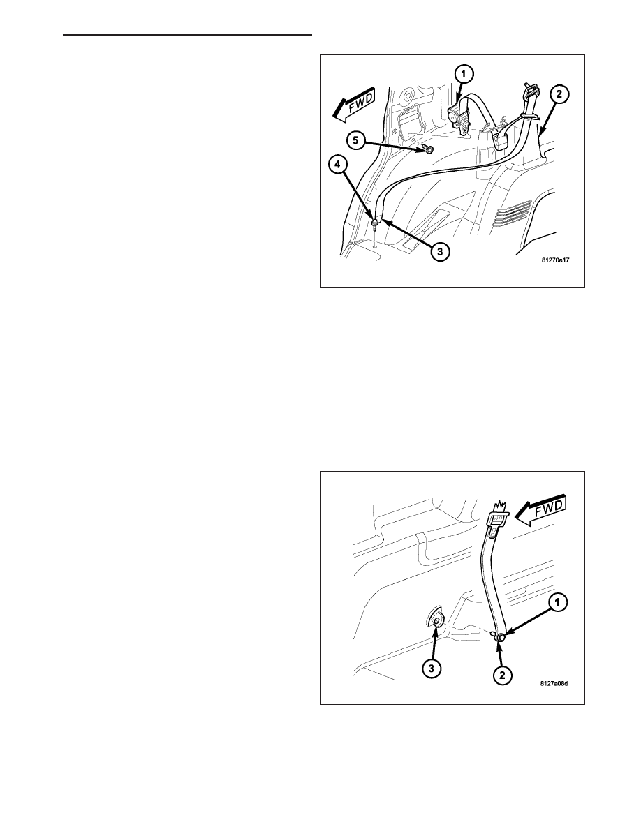
5. Remove the screw (4) that secures the lower seat

belt anchor (3) to the rear floor panel.

6. Remove the quarter trim panel (2) from the lower

C-pillar. (Refer to 23 - BODY/INTERIOR/QUARTER
TRIM PANEL - REMOVAL).

7. Route the seat belt lower anchor and turning loop

through the access hole in the quarter trim panel.

8. Remove the screw (5) that secures the retractor

bracket (1) to the lower C-pillar.

9. Lift the retractor upward far enough to disengage

the retractor tab from the engagement hole in the
C-pillar.

10. Remove the second row outboard seat belt and

retractor from the C-pillar as a unit.

THIRD ROW

WARNING: To avoid personal injury or death, during and following any seat belt or child restraint anchor
service, carefully inspect all seat belts, buckles, mounting hardware, retractors, tether straps, and anchors
for proper installation, operation, or damage. Replace any belt that is cut, frayed, or torn. Straighten any
belt that is twisted. Tighten any loose fasteners. Replace any belt that has a damaged or inoperative buckle
or retractor. Replace any belt that has a bent or damaged latch plate or anchor plate. Replace any child
restraint anchor or the unit to which the anchor is integral that has been bent or damaged. Never attempt to
repair a seat belt or child restraint component. Always replace damaged or faulty seat belt and child
restraint components with the correct, new and unused replacement parts listed in the DaimlerChrysler
Mopar Parts Catalog.

1. Move the third row seat cushion to its storage posi-

tion, but leave the third row seat back in its upright
position for easiest access to the seat belt lower
anchor (2) on the quarter inner panel (3).

2. Remove the screw (1) that secures the lower

anchor to the tapping plate on the quarter inner
panel.

HB

RESTRAINTS - SERVICE INFORMATION

8O - 517

3. Remove the D-pillar trim panel (1) from the inside

of the upper D-pillar. (Refer to 23 - BODY/INTERI-
OR/D-PILLAR TRIM - REMOVAL).

4. Route the seat belt (2) and lower anchor through

the access hole in the D-pillar trim panel.

5. Remove the screw (4) that secures the seat belt

turning loop (3) to the inside of the upper D-pillar.

6. Remove the turning loop from the D-pillar.

7. Remove the quarter trim panel from the lower

D-pillar. (Refer to 23 - BODY/INTERIOR/QUARTER
TRIM PANEL - REMOVAL).

8. Remove the screw (6) that secures the retractor

bracket (5) to the lower D-pillar.

9. Remove the third row seat belt and retractor from

the D-pillar as a unit.

INSTALLATION

FRONT

WARNING: To avoid personal injury or death, on vehicles equipped with airbags, disable the supplemental
restraint system before attempting any steering wheel, steering column, airbag, occupant classification sys-
tem, seat belt tensioner, impact sensor, or instrument panel component diagnosis or service. Disconnect
and isolate the battery negative (ground) cable, then wait two minutes for the system capacitor to discharge
before performing further diagnosis or service. This is the only sure way to disable the supplemental
restraint system. Failure to take the proper precautions could result in accidental airbag deployment.

WARNING: To avoid personal injury or death, during and following any seat belt or child restraint anchor
service, carefully inspect all seat belts, buckles, mounting hardware, retractors, tether straps, and anchors
for proper installation, operation, or damage. Replace any belt that is cut, frayed, or torn. Straighten any
belt that is twisted. Tighten any loose fasteners. Replace any belt that has a damaged or inoperative buckle
or retractor. Replace any belt that has a bent or damaged latch plate or anchor plate. Replace any child
restraint anchor or the unit to which the anchor is integral that has been bent or damaged. Never attempt to
repair a seat belt or child restraint component. Always replace damaged or faulty seat belt and child
restraint components with the correct, new and unused replacement parts listed in the DaimlerChrysler
Mopar Parts Catalog.

NOTE: The following procedure is for replacement of a faulty or damaged seat belt and retractor unit. The
front retractor also includes a seat belt tensioner. If the front seat belt or retractor is faulty or damaged, but
the seat belt tensioner is not deployed, review the recommended procedures for handling non-deployed
supplemental restraints. (Refer to 8 - ELECTRICAL/RESTRAINTS - STANDARD PROCEDURE - HANDLING
NON-DEPLOYED SUPPLEMENTAL RESTRAINTS). If the seat belt tensioner has been deployed, review the
recommended procedures for service after a supplemental restraint deployment before removing the unit
from the vehicle. (Refer to 8 - ELECTRICAL/RESTRAINTS - STANDARD PROCEDURE - SERVICE AFTER A
SUPPLEMENTAL RESTRAINT DEPLOYMENT).

8O - 518

RESTRAINTS - SERVICE INFORMATION

HB

1. Position the front seat belt and retractor (7) to the

B-pillar (4) as a unit. Be certain to engage the
engagement tab on the upper retractor bracket into
the engagement slot in the lower B-pillar.

2. Loosely install the screw (6) that secures the lower

retractor bracket to the B-pillar.

3. Install and tighten the screw (8) that secures the

upper retractor bracket to the B-pillar. Tighten the
screw to 4 N·m (35 in. lbs.).

4. Tighten the screw (6) that secures the lower retrac-

tor bracket to the B-pillar. Tighten the screw to 39
N·m (29 ft. lbs.).

5. Reconnect the body wire harness connector (5) to

the seat belt tensioner initiator on the retractor.

6. On the driver side only, reconnect the second body

wire harness connector to the seat belt switch con-
nector receptacle on the retractor.

7. Position the belt web guide (1) to the B-pillar.

8. Install and tighten the screw (3) that secures the belt web guide to the B-pillar. Tighten the screw to 4 N·m (35

in. lbs.).

9. Reinstall the lower trim onto the inside of the B-pillar. (Refer to 23 - BODY/INTERIOR/B-PILLAR LOWER TRIM

- INSTALLATION).

10. Reinstall the upper trim (1) onto the inside of the

B-pillar. (Refer to 23 - BODY/INTERIOR/B-PIL-
LAR UPPER TRIM - INSTALLATION).

11. Position the seat belt turning loop (5) onto the

height adjuster (2) on the upper B-pillar.

12. Install and tighten the screw (4) that secures the

turning loop to the height adjuster. Tighten the
screw to 39 N·m (29 ft. lbs.).

HB

RESTRAINTS - SERVICE INFORMATION

8O - 519

13. Engage the tab (2) on the lower edge of the trim

cover (3) in the slot below the screw in the turning
loop (1). Then press the upper edge of the trim
cover over the top of the turning loop until it
snaps into place.

14. Position the front seat belt lower anchor (3) to the

bracket on the outboard side of the front seat
cushion frame.

15. Install and tighten the screw (2) that secures the

lower anchor to the bracket on the outboard side
of the front seat cushion frame. Tighten the screw
to 39 N·m (29 ft. lbs.).

16. Align the seat belt anchor cover (2) to the opening

near the rear of the outboard seat side shield (3).
Using hand pressure, press firmly and evenly on
the cover until it snaps into place.

17. Do not reconnect the battery negative cable at

this time. The supplemental restraint system veri-
fication test procedure should be performed fol-
lowing

service

of

any

supplemental

restraint

system component. (Refer to 8 - ELECTRICAL/
RESTRAINTS

-

STANDARD

PROCEDURE

-

VERIFICATION TEST).

8O - 520

RESTRAINTS - SERVICE INFORMATION

HB


Content   ..  560  561  562  563   ..