Dodge Durango (HB). Manual - part 549


  Index      Dodge     Dodge Durango (HB) - service repair manual 2005 year


Search            


Content   ..  547  548  549  550   ..


Dodge Durango (HB). Manual - part 549


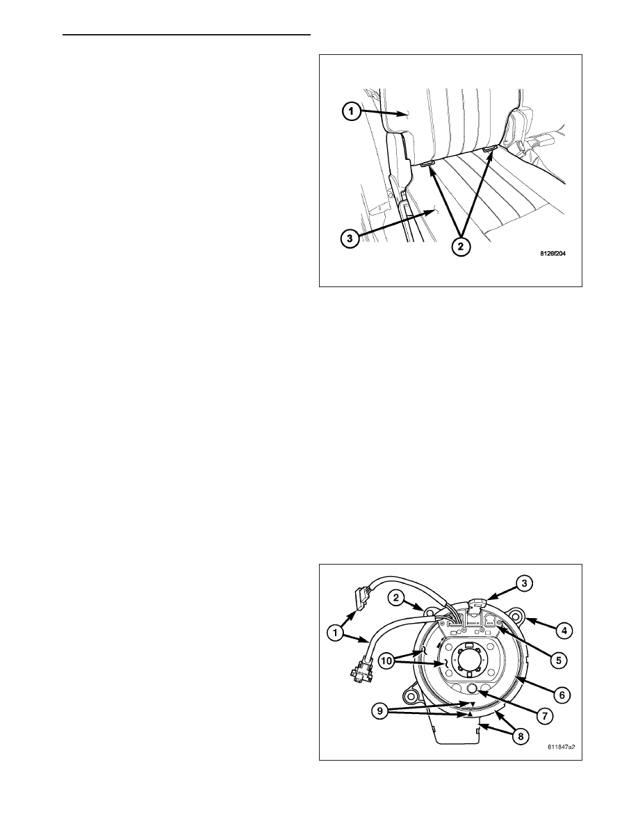
The lower anchors (2) for this model are also integral
to their respective second row outboard seat cushion
frame. These anchors are also constructed from a
heavy-gauge steel wire loop that is chrome plated and
securely welded to the seat cushion frame. They are
each accessed from the front of their respective seats,
at each side where the seat back (1) meets the seat
cushion (3). These lower anchors cannot be adjusted
or repaired and, if faulty or damaged, they must be
replaced as a unit with the second row seat cushion
frame unit.

WARNING: To avoid personal injury or death, during and following any seat belt or child restraint anchor
service, carefully inspect all seat belts, buckles, mounting hardware, retractors, tether straps, and anchors
for proper installation, operation, or damage. Replace any belt that is cut, frayed, or torn. Straighten any
belt that is twisted. Tighten any loose fasteners. Replace any belt that has a damaged or inoperative buckle
or retractor. Replace any belt that has a bent or damaged latch plate or anchor plate. Replace any child
restraint anchor or the unit to which the anchor is integral that has been bent or damaged. Never attempt to
repair a seat belt or child restraint component. Always replace damaged or faulty seat belt and child
restraint components with the correct, new and unused replacement parts listed in the DaimlerChrysler
Mopar Parts Catalog.

OPERATION

See the owner’s manual in the vehicle glove box for more information on the proper use of all of the factory-installed
child restraint anchors.

CLOCKSPRING

DESCRIPTION

The clockspring assembly is secured with two screws
onto the multi-function switch mounting housing near
the top of the steering column behind the steering
wheel. The clockspring consists of a flat, round
molded plastic case (8) with a stubby tail that hangs
below the steering column. The tail contains two con-
nector receptacles that face toward the instrument
panel. Within the plastic case is a spool-like molded
plastic rotor (10) with a large exposed hub. The upper
surface of the rotor hub has a large center hole, two
large flats, an engagement dowel with a yellow rubber
boot (7), two short pigtail wires with connectors (1),
and two connector receptacles (5) that face toward the
steering wheel.

HB

RESTRAINTS - SERVICE INFORMATION

8O - 465

The lower surface of the rotor hub has a molded plas-
tic turn signal cancel cam (3) with two lobes that is
keyed to the rotor and is secured there with four inte-
gral snap features. Within the plastic case and wound
around the rotor spool is a long ribbon-like tape that
consists of several thin copper wire leads sandwiched
between two thin plastic membranes. The outer end of
the tape terminates at the connector receptacles (4)
that face the instrument panel, while the inner end of
the tape terminates at the pigtail wires and connector
receptacles on the hub of the clockspring rotor that
face the steering wheel.

Service replacement clocksprings are shipped pre-centered and with a molded plastic locking pin (1) that snaps into
a receptacle on the rotor and is engaged between two tabs on the upper surface of the rotor case. The locking pin
secures the centered clockspring rotor to the clockspring case during shipment and handling, but must be removed
from the clockspring after it is installed on the steering column. (Refer to 8 - ELECTRICAL/RESTRAINTS/CLOCK-
SPRING - STANDARD PROCEDURE - CLOCKSPRING CENTERING).

The clockspring cannot be repaired. If the clockspring is faulty, damaged, or if the driver airbag has been deployed,
the clockspring must be replaced.

OPERATION

The clockspring is a mechanical electrical circuit component that is used to provide continuous electrical continuity
between the fixed instrument panel wire harness and the electrical components mounted on or in the rotating steer-
ing wheel. On this model the rotating electrical components include the driver airbag, the horn switch, the speed
control switches, and the remote radio switches, if the vehicle is so equipped. The clockspring case is positioned
and secured to the multi-function switch mounting housing near the top of the steering column. The connector
receptacles on the tail of the fixed clockspring case connect the clockspring to the vehicle electrical system through
two take outs with connectors from the instrument panel wire harness.

The clockspring rotor is movable and is keyed by an engagement dowel that is molded onto the rotor hub between
two fins that are cast into the lower surface of the steering wheel armature. A yellow rubber boot is installed over the
engagement dowel to eliminate contact noise between the dowel and the steering wheel. The two lobes on the turn
signal cancel cam on the lower surface of the clockspring rotor hub contact a turn signal cancel actuator of the
multi-function switch to provide automatic turn signal cancellation.

Two short, yellow-sleeved pigtail wires on the upper surface of the clockspring rotor connect the clockspring to the
multistage driver airbag, while a steering wheel wire harness connects the two connector receptacles on the upper
surface of the clockspring rotor to the horn switch feed pigtail wire connector and, if the vehicle is so equipped, to
the optional speed control and remote radio switches on the steering wheel.

Like the clockspring in a timepiece, the clockspring tape has travel limits and can be damaged by being wound too
tightly during full stop-to-stop steering wheel rotation. To prevent this from occurring, the clockspring is centered
when it is installed on the steering column. Centering the clockspring indexes the clockspring tape to the movable
steering components so that the tape can operate within its designed travel limits. However, if the clockspring is
removed from the steering column or if the steering shaft is disconnected from the steering gear, the clockspring
spool can change position relative to the movable steering components. The clockspring must be re-centered fol-
lowing completion of this service or the tape may be damaged.

Service replacement clocksprings are shipped pre-centered and with a plastic locking pin installed. This locking pin
should not be removed until the clockspring has been installed on the steering column. If the locking pin is removed
before the clockspring is installed on a steering column, the clockspring centering procedure must be performed.
(Refer to 8 - ELECTRICAL/RESTRAINTS/CLOCKSPRING - STANDARD PROCEDURE - CLOCKSPRING
CENTERING).

8O - 466

RESTRAINTS - SERVICE INFORMATION

HB

STANDARD PROCEDURE

CLOCKSPRING CENTERING

WARNING: To avoid personal injury or death, on vehicles equipped with airbags, disable the supplemental
restraint system before attempting any steering wheel, steering column, airbag, occupant classification sys-
tem, seat belt tensioner, impact sensor, or instrument panel component diagnosis or service. Disconnect
and isolate the battery negative (ground) cable, then wait two minutes for the system capacitor to discharge
before performing further diagnosis or service. This is the only sure way to disable the supplemental
restraint system. Failure to take the proper precautions could result in accidental airbag deployment.

NOTE: Before starting this procedure, be certain to turn the steering wheel until the front wheels are in the
straight-ahead position.

1. Place the front wheels in the straight-ahead posi-

tion.

2. Remove the clockspring from the steering column.

(Refer to 8 - ELECTRICAL/RESTRAINTS/CLOCK-
SPRING - REMOVAL).

3. Rotate the clockspring rotor (10) clockwise to the

end of its travel. Do not apply excessive torque.

4. From the end of the clockwise travel, rotate the

rotor about two and one-half turns counterclock-
wise. The engagement dowel and yellow rubber
boot (7) should end up at the bottom, and the
arrows on the clockspring rotor and case (9) should
be in alignment.

5. The clockspring is now centered. Secure the clock-

spring rotor to the clockspring case to maintain
clockspring centering until it is reinstalled on the steering column.

6. The front wheels should still be in the straight-ahead position. Reinstall the clockspring onto the steering column.

(Refer to 8 - ELECTRICAL/RESTRAINTS/CLOCKSPRING - INSTALLATION).

REMOVAL

WARNING: To avoid personal injury or death, on vehicles equipped with airbags, disable the supplemental
restraint system before attempting any steering wheel, steering column, airbag, occupant classification sys-
tem, seat belt tensioner, impact sensor, or instrument panel component diagnosis or service. Disconnect
and isolate the battery negative (ground) cable, then wait two minutes for the system capacitor to discharge
before performing further diagnosis or service. This is the only sure way to disable the supplemental
restraint system. Failure to take the proper precautions could result in accidental airbag deployment.

NOTE: Before starting this procedure, be certain to turn the steering wheel until the front wheels are in the
straight-ahead position.

HB

RESTRAINTS - SERVICE INFORMATION

8O - 467

1. Place the front wheels in the straight ahead posi-

tion.

2. Disconnect and isolate the battery negative cable.

3. Remove the driver airbag from the steering wheel.

(Refer to 8 - ELECTRICAL/RESTRAINTS/DRIVER
AIRBAG - REMOVAL).

4. Disconnect the steering wheel wire harness con-

nectors from the upper clockspring connector
receptacles.

CAUTION: Be certain that the screws that secure
the steering wheel puller to the steering wheel are
fully engaged in the steering wheel armature with-
out passing through the steering wheel and dam-
aging the clockspring.

5. Remove the steering wheel (1) from the steering column. (Refer to 19 - STEERING/COLUMN/STEERING

WHEEL - REMOVAL).

6. Grasp the tilt steering column knob (3) firmly and pull it straight rearward to remove it from the tilt adjuster lever

on the left side of the column.

7. From below the steering column, remove the two

outboard screws that secure the upper column
shroud (1) to the lower shroud (3).

8. Using hand pressure, push gently inward on both

sides of the upper shroud above the parting line of
the lower shroud to release the snap features that
secure the two shroud halves to each other.

9. Remove the upper shroud from the lower shroud

and the steering column.

10. Remove the one center screw that secures the

lower shroud to the steering column (4).

11. Remove the lower shroud from the steering col-

umn.

12. Disconnect the two instrument panel wire harness

connectors from the two connector receptacles
located below the steering column on the back of
the clockspring housing.

8O - 468

RESTRAINTS - SERVICE INFORMATION

HB


Content   ..  547  548  549  550   ..