Dodge Durango (HB). Manual - part 529


  Index      Dodge     Dodge Durango (HB) - service repair manual 2005 year


Search            


Content   ..  527  528  529  530   ..


Dodge Durango (HB). Manual - part 529


U0019–CAN B BUS (CONTINUED)

4.

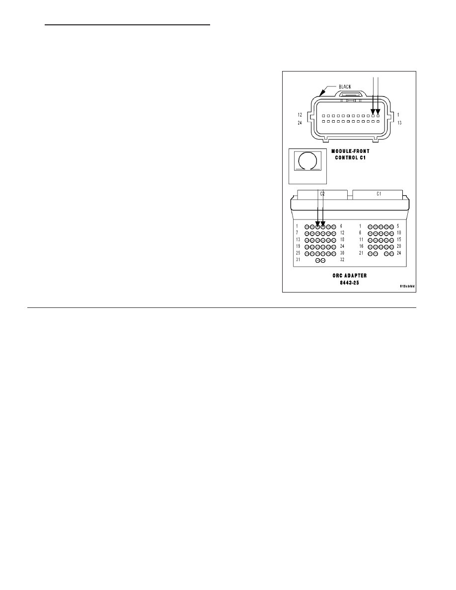
CHECK (D54) CAN B BUS (–) CIRCUIT FOR AN OPEN

Measure the resistance of the (D54) CAN B Bus (–) circuit between
the Front Control Module C1 connector and the ORC C2 connector.

Is the resistance below 2.0 ohms?

Yes

>> Replace the ORC in accordance with the Service Informa-

tion.

Perform ORC VERIFICATION TEST - VER 1.

No

>> Repair the (D54) CAN B Bus (–) circuit for an open.

Perform ORC VERIFICATION TEST - VER 1.

HB

RESTRAINTS - ELECTRICAL DIAGNOSTICS

8O - 385

U0020-CAN B BUS OFF PERFORMANCE

MS-CAN B D54 AND D55

8O - 386

RESTRAINTS - ELECTRICAL DIAGNOSTICS

HB

U0020-CAN B BUS OFF PERFORMANCE (CONTINUED)

For the Air Bag System circuit diagram (Refer to 8 - ELECTRICAL/RESTRAINTS - SCHEMATICS AND DIA-
GRAMS).

For a complete wiring diagram Refer to Section 8W.

When Monitored:
Continuously

Set Condition:
Whenever the CAN B Bus (+) or CAN B Bus (-) circuit is open, shorted to voltage, or shorted to ground.

Possible Causes

ACTIVE U0020 CAN B BUS DTC IN OCCUPANT CLASSIFICATION MODULE

(D55) CAN B BUS (+) CIRCUIT OPEN

(D54) CAN B BUS (-) CIRCUIT OPEN

OCCUPANT CLASSIFICATION MODULE (OCM)

Diagnostic Test

1.

VERIFY DTC U0020–CAN B BUS IS ACTIVE

Turn the ignition on.

With the scan tool, read Occupant Classification Module (OCM) DTCs.

Does the scan tool display active: U0019–CAN B BUS?

Yes

>> Go To 2

No

>> If the DTC is stored, check for an intermittent condition by

inspecting the related wiring harness for chaffed, pierced,
pinched, and partially broken wires. Also, inspect the
related connectors for broken, bent, pushed out, spread,
corroded, or contaminated terminals.

Perform ORC VERIFICATION TEST – VER 1.

HB

RESTRAINTS - ELECTRICAL DIAGNOSTICS

8O - 387

U0020-CAN B BUS OFF PERFORMANCE (CONTINUED)

2.

CHECK FOR ACTIVE CAN B BUS RELATED DTCS IN THE FRONT CONTROL MODULE (FCM)

With the scan tool, read Front Control Module (FCM) DTCs

Does the scan tool display any active CAN B BUS related
DTCs?

Yes

>> Diagnose and repair the DTC(s). (Refer to 8 - ELECTRI-

CAL/ELECTRONIC CONTROL MODULES - DIAGNOSIS
AND TESTING).

No

>> Go To 3

3.

CHECK (D55) CAN B BUS (+) CIRCUIT FOR AN OPEN

Turn the ignition off.

Disconnect the negative battery cable.

Disconnect the OCM C1 connector.

Disconnect the Front Control Module (FCM) C1 connector.

Measure the resistance of the (D55) CAN B Bus (+) circuit between
the Front Control Module C1 connector and the OCM C1 connector.

Is the resistance below 2.0 ohms?

Yes

>> Go To 4

No

>> Repair the (D55) CAN B Bus (+) circuit for an open.

Perform ORC VERIFICATION TEST - VER 1.

8O - 388

RESTRAINTS - ELECTRICAL DIAGNOSTICS

HB


Content   ..  527  528  529  530   ..