Dodge Durango (HB). Manual - part 519
B212C-IGNITION RUN/START INPUT CIRCUIT OPEN (CONTINUED)
For the Airbag System circuit diagram (Refer to 8 - ELECTRICAL/RESTRAINTS - SCHEMATICS AND DIAGRAMS).
For a complete wiring diagram Refer to Section 8W.
•
When Monitored:
With the ignition in the Run-Start position.
•
Set Condition:
If voltage on the (F201) Fused Ignition Switch Output (Run-Start) circuit drops below 6.0 volts.
Possible Causes
PASSENGER AIRBAG (PAB) INDICATOR RUN-START FUSE OPEN
(F201) FUSED IGNITION SWITCH OUTPUT (RUN-START) CIRCUIT SHORTED TO GROUND
(F201) FUSED IGNITION SWITCH OUTPUT (RUN-START) CIRCUIT OPEN
(F941) IGNITION SWITCH OUTPUT (RUN-START) CIRCUIT OPEN
PASSENGER AIRBAG ON/OFF INDICATOR LAMP
OCCUPANT CLASSIFICATION MODULE (OCM)
OCCUPANT RESTRAINT CONTROLLER (ORC)
Diagnostic Test
1.
VERIFY THAT DTC B212C IGNITION RUN/START INPUT CIRCUIT OPEN IS ACTIVE
NOTE: Ensure the battery is fully charged.
NOTE: When reconnecting Airbag system components, the igni-
tion must be turned off and the battery must be disconnected.
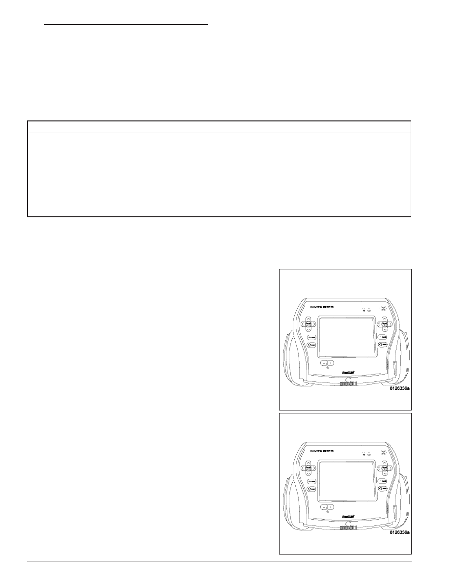
Turn the ignition on.
With the scan tool, read Occupant Restraint Controller (ORC) DTCs.
Does the scan tool display active: B212C IGNITION RUN/START
INPUT CIRCUIT OPEN?
Yes
>> Go To 2
No
>> Go To 10
HB
RESTRAINTS - ELECTRICAL DIAGNOSTICS
8O - 345