Dodge Durango (HB). Manual - part 389


  Index      Dodge     Dodge Durango (HB) - service repair manual 2005 year


Search            


Content   ..  387  388  389  390   ..


Dodge Durango (HB). Manual - part 389


5.

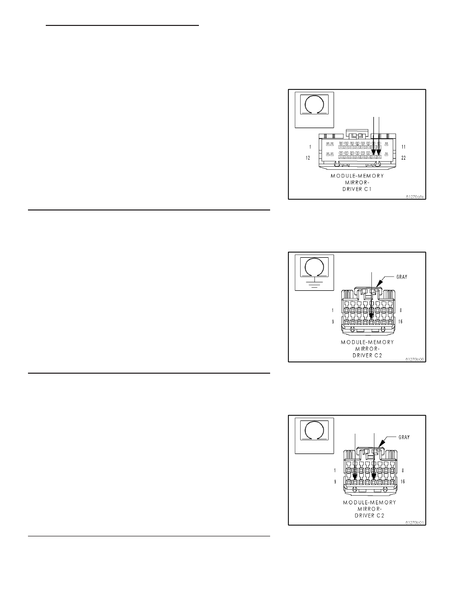
(G161) DRIVER DOOR LOCK SWITCH MUX CIRCUIT
SHORTED TO THE (G775) DRIVER DOOR LOCK SWITCH
RETURN CIRCUIT

Measure the resistance between the (G161) Driver Door Lock Switch
Mux circuit and the (G775) Driver Door Lock Switch Return circuit in
the Memory Mirror Module connector.

Is the resistance below 10000.0 ohms?

Yes

>> Repair the (G161) Driver Door Lock Switch Mux circuit for

a short to the (G775) Driver Door Lock Switch Return cir-
cuit.

Perform BODY VERIFICATION TEST - VER 1.

No

>> Go to 6

6.

(P339) MEMORY SELECT SWITCH MUX CIRCUIT SHORT TO
THE GROUND

Disconnect the Driver Memory Mirror Module C2 connector.

Measure the resistance between ground and the (P339) Memory
Select Switch Mux circuit.

Is the resistance below 10000.0 ohms?

Yes

>> Repair the Memory Select Switch Mux wire for a short to

ground.

Perform the BODY VERIFICATION TEST - VER 1.

No

>> Go to 7

7.

(P339) MEMORY SELECT SWITCH MUX CIRCUIT SHORT TO
THE (G920) MEMORY SELECT SWITCH RETURN CIRCUIT

Measure the resistance between the (P339) Memory Select Switch
Mux circuit and the (G920) Memory Select Switch Return circuit in the
Driver Memory Mirror Module C2 connector.

Is the resistance below 10000.0 ohms?

Yes

>> Repair the (P339) Memory Select Switch Mux circuit for a

short to the (G920) Memory Select Switch return circuit.

Perform BODY VERIFICATION TEST - VER 1.

No

>> Replace the Driver Memory Mirror Module.

Perform BODY VERIFICATION TEST - VER 1.

HB

POWER MIRRORS - ELECTRICAL DIAGNOSTICS

8N - 69

B1D4D–MEMORY SWITCH INPUT CIRCUIT STUCK – MEMORY MIRROR MODULE — (CONTINUED)

8N - 70

POWER MIRRORS - ELECTRICAL DIAGNOSTICS

HB

U1000–CAN B BUS (+) CIRCUIT– MEMORY MIRROR MODULE

For a complete wiring diagram Refer to Section 8W.

When Monitored:
Continuously

Set Condition:
Whenever the Can B Bus (+) circuit is open, shorted to voltage or shorted to ground, this code will set.

Possible Causes

CAN B BUS (+) DTC’s IN FRONT CONTROL MODULE

(D55) CAN B BUS (+) CIRCUIT OPEN

MEMORY MIRROR MODULE

Diagnostic Test

1.

TEST FOR INTERMITTENT CONDITION

Turn the ignition on.

With the scan tool, record and erase DTC’s

Cycle the ignition from on to off 3 times.

Turn the ignition on.

With the scan tool, read DTC’s.

Does the scan tool display U1000 CAN B BUS (+) CIRCUIT?

Yes

>> Go To 2

No

>> The conditions that caused this code to set are not

present at this time. Using the wiring diagram/schematic
as a guide, inspect the wiring and connectors.

2.

CHECK FRONT CONTROL MODULE DTC’s

With the scan tool, read Front Control Module DTC’s

Does the scan tool display any CAN B BUS DTC’s – ACTIVE?

Yes

>> Refer to the symptom list for problems related to Commu-

nication in the ELECTRICAL.– ELECTRONIC CONTROL
MODULES – ELECTRICAL DIAGNOSES section.

No

>> Go to 3

HB

POWER MIRRORS - ELECTRICAL DIAGNOSTICS

8N - 71

U1000–CAN B BUS (+) CIRCUIT– MEMORY MIRROR MODULE —

(CONTINUED)

3.

CAN B BUS (+) CIRCUIT OPEN

Turn the ignition off.

Disconnect the appropriate Memory Mirror Module C1 connector.

Disconnect the Front Control Module C1 connector.

Measure the resistance of the (D55) Can B Bus (+) circuit between
the Front Control Module C1 connector and the Memory Mirror Mod-
ule connector.

Is the resistance below 2.0 ohms?

Yes

>> Replace the Memory Mirror Module.

Perform BODY VERIFICATION TEST - VER 1.

No

>> Repair the Can B Bus (+) circuit for an open.

Perform BODY VERIFICATION TEST - VER 1.

8N - 72

POWER MIRRORS - ELECTRICAL DIAGNOSTICS

HB

U1000–CAN B BUS (+) CIRCUIT– MEMORY MIRROR MODULE —

(CONTINUED)


Content   ..  387  388  389  390   ..