Index Dodge Dodge Durango (HB) - service repair manual 2005 year
Search
Content .. 364 365 366 367 ..
Dodge Durango (HB). Manual - part 366
HB
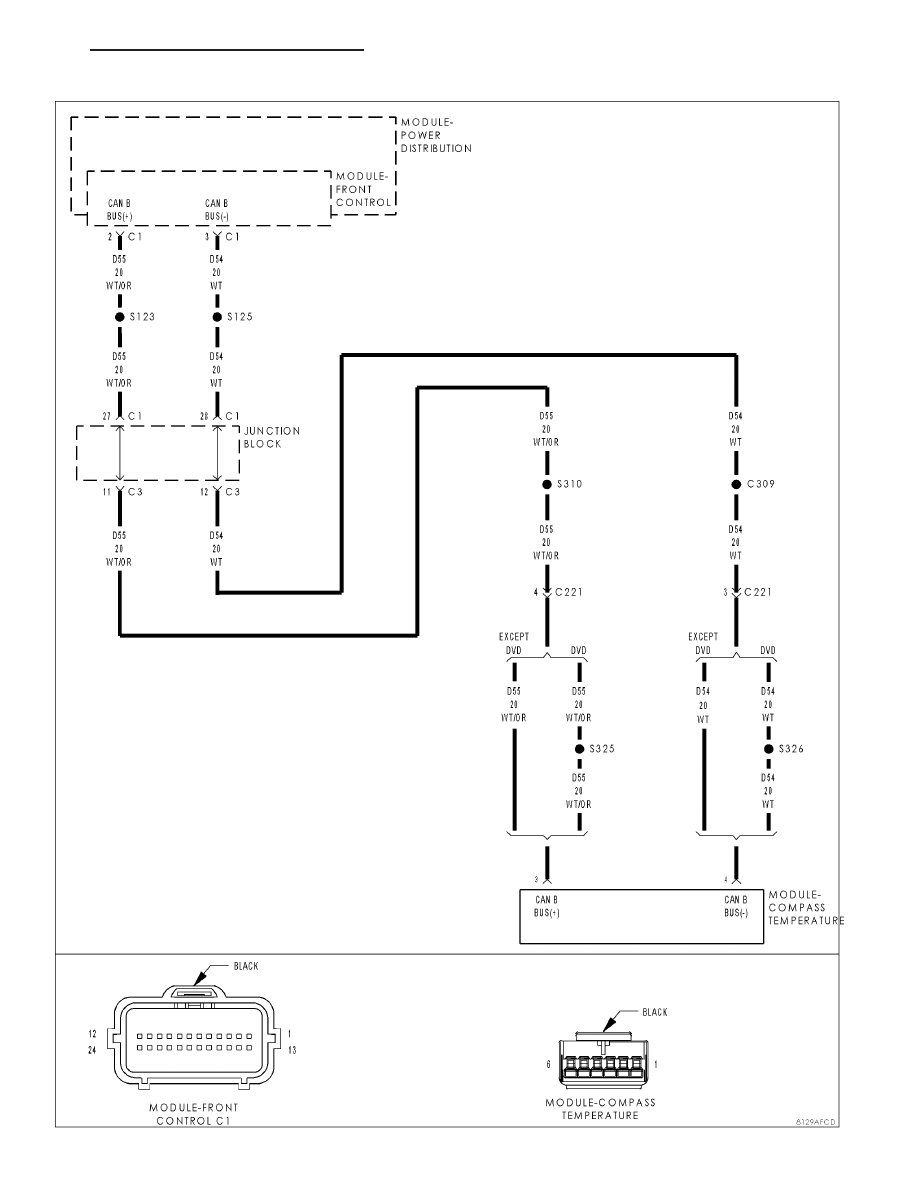
OVERHEAD CONSOLE - ELECTRICAL DIAGNOSTICS
8M - 17
U0019–CAN B BUS