Dodge Durango (HB). Manual - part 363
HB
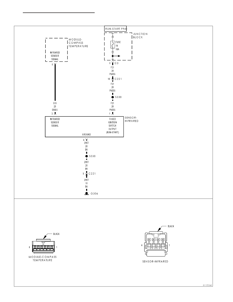
OVERHEAD CONSOLE - ELECTRICAL DIAGNOSTICS
8M - 5
B1035 - INFRARED TEMPERATURE SENSOR INPUT CIRCUIT HIGH
|
|
|
HB OVERHEAD CONSOLE - ELECTRICAL DIAGNOSTICS 8M - 5 B1035 - INFRARED TEMPERATURE SENSOR INPUT CIRCUIT HIGH |