Dodge Durango (HB). Manual - part 343
 

  Index      Dodge     Dodge Durango (HB) - service repair manual 2005 year


Search            


Content   ..  341  342  343  344   ..


Dodge Durango (HB). Manual - part 343


1. Disconnect and isolate the battery negative cable.

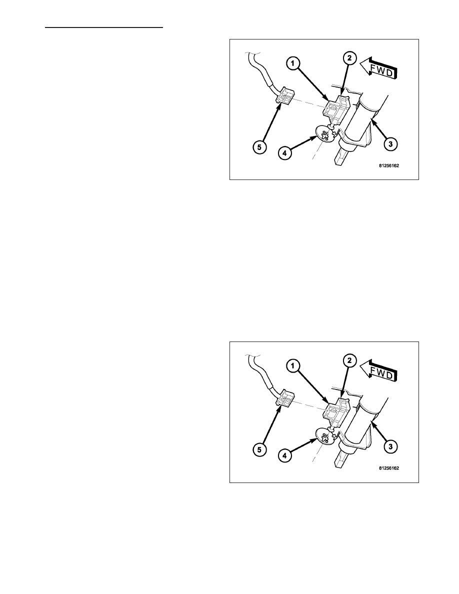
2. Locate the brake lamp switch (1) near the support

bracket on the lower steering column (3).

3. Disconnect the wire harness connector (5) from the

brake lamp switch.

4. Rotate the brake lamp switch housing clockwise

about 30 degrees to align the tabs on the switch
locking collar with the keyed hole in the switch
mounting bracket (4).

5. Pull the switch straight back from the keyed hole to

remove it from the bracket.

CAUTION: The brake lamp switch self-adjusting
switch plunger is a one time only feature. If the
switch is removed from the mounting bracket, it
MUST be replaced with a new switch.

6. Discard the removed brake lamp switch

.

INSTALLATION

WARNING: To avoid personal injury or death, on vehicles equipped with airbags, disable the supplemental
restraint system before attempting any steering wheel, steering column, airbag, occupant classification sys-
tem, seat belt tensioner, impact sensor, or instrument panel component diagnosis or service. Disconnect
and isolate the battery negative (ground) cable, then wait two minutes for the system capacitor to discharge
before performing further diagnosis or service. This is the only sure way to disable the supplemental
restraint system. Failure to take the proper precautions could result in accidental airbag deployment.

CAUTION: The brake lamp switch self-adjusting switch plunger is a one time only feature. If the switch is
removed from the mounting bracket, it MUST be replaced with a new switch.

1. Depress and hold the brake pedal in the depressed

position.

2. Align the tabs on the brake lamp switch locking col-

lar with the keyed hole in the switch mounting
bracket (4) on the lower steering column (3).

3. Insert the tabs on the brake lamp switch locking

collar through the keyed hole in the switch mount-
ing bracket until the switch housing (1) is firmly
seated against the bracket.

4. Rotate the switch housing counterclockwise about

30 degrees to engage the tabs on the locking collar
with the switch mounting bracket.

CAUTION: Do not release or pull up on the brake
pedal before the switch plunger adjustment has
been completed.

5. Release the brake pedal, but do not pull it upward.

6. Rotate the plunger adjustment release lever (2) clockwise until it locks into place. The lever should be parallel to

the brake lamp switch connector receptacle. This action will set the switch plunger length to a final adjustment
position and cannot be undone. If not performed properly the first time, a new brake lamp switch must be
installed.

7. Reconnect the wire harness connector (5) to the brake lamp switch.

HB

LAMPS/LIGHTING - EXTERIOR - SERVICE INFORMATION

8L - 91

8. Reconnect the battery negative cable.

LAMP-HIGH MOUNTED STOP

REMOVAL

BULB

1. Disconnect and isolate the battery negative cable.

2. Remove the Center High Mounted Stop Lamp

(CHMSL) (1) from the liftgate header panel. (Refer
to 8 - ELECTRICAL/LAMPS/LIGHTING - EXTERI-
OR/CENTER HIGH MOUNTED STOP LAMP -
REMOVAL).

3. Disconnect the wire harness connector (2) from the

socket (3) on the back of the CHMSL housing.

4. Firmly grasp the socket on the back of the housing

and rotate it counterclockwise about 30 degrees to
unlock it.

5. Pull the socket and bulb straight out from the

keyed opening in the housing.

6. Pull the base of the bulb straight out of the socket.

LAMP

1. Disconnect and isolate the battery negative cable.

2. Remove the two screws (2) that secure the Center

High Mounted Stop Lamp (CHMSL) (1) to the lift-
gate header panel (3).

3. Pull the CHMSL away from the liftgate far enough

to access and disconnect the wire harness connec-
tor (5) from the lamp socket.

4. Remove the CHMSL from the liftgate.

INSTALLATION

BULB

CAUTION: Always use the correct bulb size and type for replacement. An incorrect bulb size or type may
overheat and cause damage to the lamp, the socket and/or the lamp wiring.

8L - 92

LAMPS/LIGHTING - EXTERIOR - SERVICE INFORMATION

HB

1. Align the base of the bulb with the CHMSL socket

(3).

2. Push the bulb straight into the socket until the base

is firmly seated.

3. Align the socket and bulb with the keyed opening

on the back of CHMSL housing (1).

4. Insert the socket and bulb into the housing until the

socket is firmly seated.

5. Rotate the socket clockwise about 30 degrees to

lock it into place.

6. Reconnect the wire harness connector (2) to the

socket.

7. Reinstall the CHMSL onto the liftgate header panel.

(Refer to 8 - ELECTRICAL/LAMPS/LIGHTING -
EXTERIOR/CENTER

HIGH

MOUNTED

STOP

LAMP - INSTALLATION).

8. Reconnect the battery negative cable.

LAMP

1. Check to be certain that the two J-nuts (4) are

properly positioned on the liftgate header inner
panel.

2. Position the Center High Mounted Stop Lamp

(CHMSL) (1) near the liftgate header panel (3)
opening.

3. Reconnect the wire harness connector (5) to the

CHMSL socket.

4. Install and tighten the two screws (2) that secure

the CHMSL to the liftgate header panel. Tighten the
screws to 2 N·m (20 in. lbs.).

5. Reconnect the battery negative cable.

FRONT FOG LAMP

REMOVAL

BULB

CAUTION: Do not contaminate the bulb glass by touching it with your fingers or by allowing it to contact
other oily surfaces. Shortened bulb life will result.

HB

LAMPS/LIGHTING - EXTERIOR - SERVICE INFORMATION

8L - 93

1. Disconnect and isolate the battery negative cable.

2. Reach under and behind the front fascia to access

the front fog lamp housing (1) on the back of the
front bumper support (4).

3. Disconnect the wire harness connector (3) from the

fog lamp socket (2).

4. Firmly grasp the socket on the back of the housing

and rotate it counterclockwise about 30 degrees to
unlock it.

5. Pull the socket and bulb straight out from the

keyed opening in the housing.

6. Pull the base of the bulb straight out of the socket.

LAMP

1. Disconnect and isolate the battery negative cable.

2. Reach under and behind the front fascia to access

the front fog lamp housing (4) on the back of the
front bumper support (2).

3. Disconnect the wire harness connector from the

fog lamp bulb socket.

4. Remove the front fascia from the front bumper sup-

port.

(Refer

to

13

-

FRAME

&

BUMPERS/

BUMPERS/FRONT FASCIA - REMOVAL).

5. Unscrew the adjustment screw (1) at the top of the

fog lamp until it is disengaged from the bumper
support.

6. Insert a trim stick or another suitable wide flat-

bladed tool, between either side of the lamp and
the side of the lamp seat in the bumper support.

7. Carefully pry the pivot pin on either side of the

lamp out of its receptacle in the stanchion (3)
within the seat of the bumper support.

8. Remove the lamp from the bumper support.

INSTALLATION

BULB

CAUTION: Always use the correct bulb size and type for replacement. An incorrect bulb size or type may
overheat and cause damage to the lamp, the socket and/or the lamp wiring.

CAUTION: Do not contaminate the bulb glass by touching it with your fingers or by allowing it to contact
other oily surfaces. Shortened bulb life will result.

8L - 94

LAMPS/LIGHTING - EXTERIOR - SERVICE INFORMATION

HB


Content   ..  341  342  343  344   ..