Dodge Durango (HB). Manual - part 342
1. Tape a line on a level floor 7.62 meters (25 feet) away from and parallel to the flat wall that will be used as the
lamp alignment screen. The level floor will be used as the horizontal zero reference.
2. An adjacent wall or floor member that is perpendicular to the alignment screen can be used as the vertical zero
reference. If there is no adjacent wall or floor member that is perpendicular to the screen, tape a second line on
the floor perpendicular to both the alignment screen and the first line, and outboard of either side of where the
vehicle will be positioned. This will be used as the vertical zero reference.
3. Position the vehicle so that the side of the vehicle is parallel to the vertical zero reference, and so that the front
of the lamp lenses are in the vertical plane of the parallel line taped on the floor 7.62 meters (25 feet) away from
the screen.
4. Rock the vehicle side-to-side three times to allow the suspension to stabilize.
5. Jounce the front suspension three times by pushing downward on the front bumper and releasing.
6. Measure the distance between the optical center of one of the lamps being aimed (head or fog) and the floor
(horizontal zero reference). Transfer this measurement to the alignment screen with a piece of tape placed hor-
izontally to the floor. This line will be used as the lamp horizontal reference.
7. Measure the distance between the vertical zero reference and the optical center of the nearest lamp being aimed
(head or fog). Transfer this measurement to the alignment screen with a piece of tape placed vertically across
the appropriate (head or fog) lamp horizontal reference. This is the centerline reference for the first lamp.
8. Measure the distance on center between the first and the second lamp being aimed. Transfer this measurement
to the alignment screen with a second piece of tape placed vertically across the appropriate (head or fog) lamp
horizontal reference. This is the centerline reference for the second lamp.
HEADLAMP ALIGNMENT
NOTE: Due to the linear nature of the headlamp cutoff, a properly aimed low beam headlamp will project the
top edge of the high intensity pattern on the alignment screen from the horizontal line to 50 millimeters (2
inches) below the horizontal line. No horizontal (right/left) adjustment is required for this headlamp beam
pattern. The high beam pattern will be correct when the low beams are properly aimed.
1. Turn the headlamps On and select the Low beams.
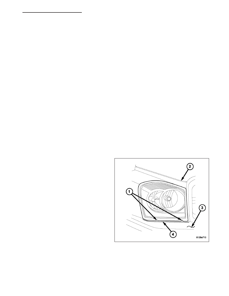
2. Rotate the headlamp vertical adjustment screw (4)
on each lamp to adjust the beam height as
required.
HB
LAMPS/LIGHTING - EXTERIOR - SERVICE INFORMATION
8L - 87