Dodge Durango (HB). Manual - part 312


  Index      Dodge     Dodge Durango (HB) - service repair manual 2005 year


Search            


Content   ..  310  311  312  313   ..


Dodge Durango (HB). Manual - part 312


CLUSTER LENS, HOOD, AND MASK

1. Disconnect and isolate the battery negative cable.

2. Remove the instrument cluster from the instrument

panel. (Refer to 8 - ELECTRICAL/INSTRUMENT
CLUSTER - REMOVAL).

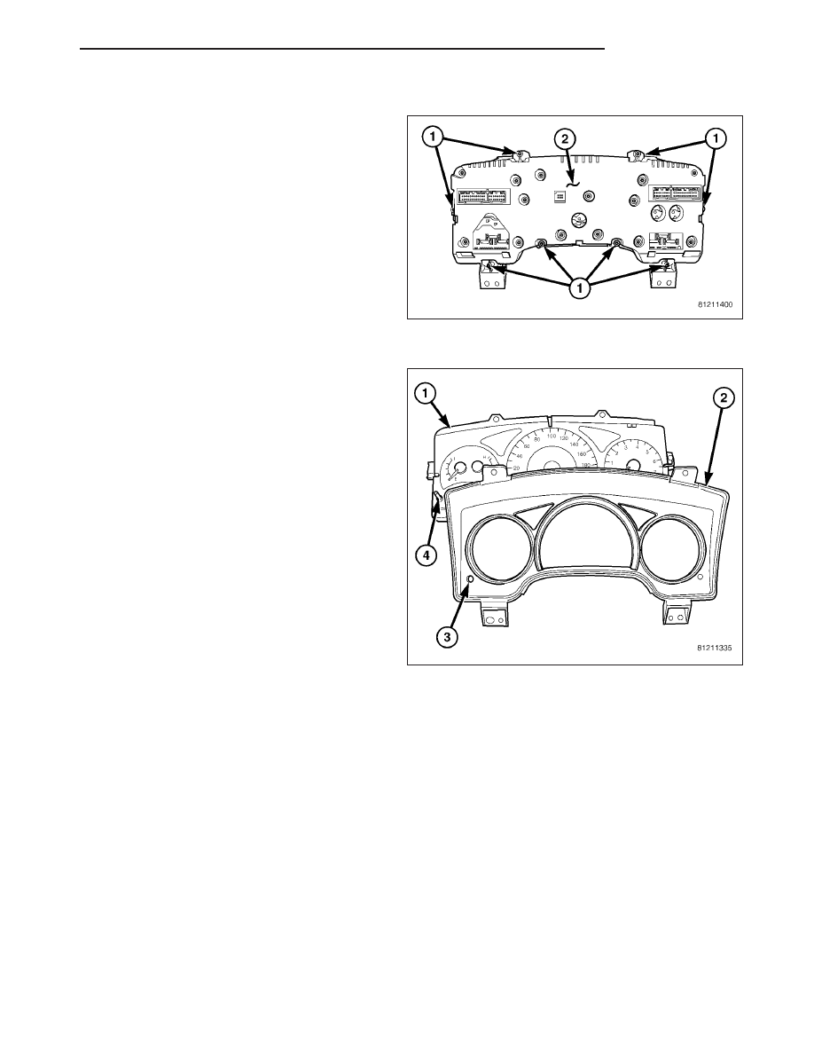
3. From the back of the instrument cluster (2), remove

the eight screws (1) around the outer perimeter of
the rear cover that secure the lens, hood, and
mask unit to the cluster housing.

4. Remove the lens, hood, and mask unit (2) from the

face of the instrument cluster (1).

ASSEMBLY

WARNING: To avoid personal injury or death, on vehicles equipped with airbags, disable the supplemental
restraint system before attempting any steering wheel, steering column, airbag, occupant classification sys-
tem, seat belt tensioner, impact sensor, or instrument panel component diagnosis or service. Disconnect
and isolate the battery negative (ground) cable, then wait two minutes for the system capacitor to discharge
before performing further diagnosis or service. This is the only sure way to disable the supplemental
restraint system. Failure to take the proper precautions could result in accidental airbag deployment.

NOTE: The cluster lens, hood and mask unit is the only component of the instrument cluster used in this
vehicle that is serviced separately. Following is the procedure for assembling this component to the instru-
ment cluster.

HB

CLUSTER

8J - 45

CLUSTER LENS, HOOD, AND MASK

1. Position the cluster lens, hood, and mask unit (2)

over the face of the instrument cluster (1). Be cer-
tain that the odometer/trip odometer switch button
(4) is inserted through the proper clearance holes
(3) in the mask and the lens.

2. From the back of the instrument cluster (2), install

and tighten the eight screws (1) around the outer
perimeter of the rear cover that secure the lens,
hood, and mask unit to the cluster housing. Tighten
the screws to 1 N·m (10 in. lbs.).

3. Reinstall the instrument cluster onto the instrument

panel. (Refer to 8 - ELECTRICAL/INSTRUMENT
CLUSTER - INSTALLATION).

4. Reconnect the battery negative cable.

INSTALLATION

WARNING: To avoid personal injury or death, on vehicles equipped with airbags, disable the supplemental
restraint system before attempting any steering wheel, steering column, airbag, occupant classification sys-
tem, seat belt tensioner, impact sensor, or instrument panel component diagnosis or service. Disconnect
and isolate the battery negative (ground) cable, then wait two minutes for the system capacitor to discharge
before performing further diagnosis or service. This is the only sure way to disable the supplemental
restraint system. Failure to take the proper precautions could result in accidental airbag deployment.

8J - 46

CLUSTER

HB

1. Position the instrument cluster close enough to the

instrument panel to reconnect the instrument panel
wire harness connectors (2) to the connector
receptacles (1) on the back of the cluster housing.

2. Position the instrument cluster (2) into the instru-

ment panel (1).

3. Install and tighten the four screws (3) that secure

the instrument cluster to the instrument panel.
Tighten the screws to 2 N·m (17 in. lbs.).

4. Reinstall the cluster bezel onto the instrument

panel. (Refer to 23 - BODY/INSTRUMENT PANEL/
CLUSTER BEZEL - INSTALLATION).

5. Reconnect the battery negative cable.

NOTE: Certain indicators in this instrument cluster
are automatically configured. This feature allows
those indicators to be activated or deactivated for
compatibility with certain optional equipment. If a
problem is noted that involves improper illumina-
tion of the cruise indicator, the electronic throttle
control indicator, the tow/haul indicator, the ser-
vice four-wheel drive indicator, the four-wheel
drive low indicator, the four-wheel drive lock indi-
cator, the transmission overtemp indicator, the security indicator or the gear selector indicator, disconnect
and isolate the battery negative cable. After about five minutes, reconnect the battery negative cable and
turn the ignition switch to the On position. The instrument cluster should automatically relearn the equip-
ment in the vehicle and properly configure the configurable indicators accordingly.

ABS INDICATOR

DESCRIPTION

An Antilock Brake System (ABS) indicator is standard
equipment on all instrument clusters. This indicator
serves both the standard equipment Rear Wheel Anti-
Lock (RWAL) and optional equipment 4-Wheel Anti-
Lock (4WAL) brake systems. This indicator is located near the upper edge of the instrument cluster, between the
tachometer and the speedometer.

HB

CLUSTER

8J - 47

The ABS indicator consists of a stencil-like cutout of the International Control and Display Symbol icon for “Failure
of Anti-lock Braking System” in the opaque layer of the instrument cluster overlay. The dark outer layer of the over-
lay prevents the indicator from being clearly visible when it is not illuminated. An amber Light Emitting Diode (LED)
behind the cutout in the opaque layer of the overlay causes the icon to appear in amber through the translucent
outer layer of the overlay when the indicator is illuminated from behind by the LED, which is soldered onto the
instrument cluster electronic circuit board. The ABS indicator is serviced as a unit with the instrument cluster.

OPERATION

The ABS indicator gives an indication to the vehicle operator when the ABS system is faulty or inoperative. This
indicator is controlled by a transistor on the instrument cluster circuit board based upon cluster programming and
electronic messages received by the cluster from the Controller Antilock Brake (CAB) over the Controller Area Net-
work (CAN) data bus.

The ABS indicator Light Emitting Diode (LED) is completely controlled by the instrument cluster logic circuit, and that
logic will only allow this indicator to operate when the instrument cluster receives a battery current input on the
fused ignition switch output (run-start) circuit. Therefore, the LED will always be off when the ignition switch is in any
position except On or Start. The LED only illuminates when it is provided a path to ground by the instrument cluster
transistor. The instrument cluster will turn on the ABS indicator for the following reasons:

Bulb Test - Each time the ignition switch is turned to the On position the ABS indicator is illuminated for about
four seconds as a bulb test. The entire bulb test is a function of the CAB.

ABS Lamp-On Message - Each time the cluster receives a lamp-on message from the CAB, the ABS indi-
cator will be illuminated. The indicator remains illuminated until the cluster receives a lamp-off message from
the CAB, or until the ignition switch is turned to the Off position, whichever occurs first.

Communication Error - If the cluster receives no lamp-on or lamp-off messages from the CAB for five con-
secutive message cycles, the ABS indicator is illuminated. The indicator remains illuminated until the cluster
receives a valid message from the CAB, or until the ignition switch is turned to the Off position, whichever
occurs first.

Actuator Test - Each time the instrument cluster is put through the actuator test, the ABS indicator will be
turned on, then off again during the bulb check portion of the test to confirm the functionality of the LED and
the cluster control circuitry.

ABS Diagnostic Test - The ABS indicator is blinked on and off by lamp-on and lamp-off messages from the
CAB during the performance of the ABS diagnostic tests.

The CAB continually monitors the ABS circuits and sensors to decide whether the system is in good operating con-
dition. The CAB then sends the proper lamp-on or lamp-off messages to the instrument cluster. If the CAB sends a
lamp-on message after the bulb test, it indicates that the CAB has detected a system malfunction and/or that the
ABS system has become inoperative. The CAB will store a Diagnostic Trouble Code (DTC) for any malfunction it
detects. Each time the ABS indicator fails to light due to an open or short in the cluster ABS indicator circuit, the
cluster sends a message notifying the CAB of the condition, then the instrument cluster and the CAB will each store
a DTC.

For proper diagnosis of the antilock brake system, the CAB, the CAN data bus, or the electronic message inputs to
the instrument cluster that control the ABS indicator, a diagnostic scan tool is required. Refer to the appropriate
diagnostic information.

AIRBAG INDICATOR

DESCRIPTION

An airbag indicator is standard equipment on all
instrument clusters. However, the instrument cluster
can be programmed to disable this indicator on vehi-
cles that are not equipped with the airbag system,
which is not available in some markets. This indicator
is located in the center of the speedometer, in the area above and left of the speedometer needle hub.

The airbag indicator consists of a stencil-like cutout of the International Control and Display Symbol icon for “Airbag”
in the opaque layer of the instrument cluster overlay. The dark outer layer of the overlay prevents the indicator from

8J - 48

CLUSTER

HB


Content   ..  310  311  312  313   ..