Dodge Durango (HB). Manual - part 304


  Index      Dodge     Dodge Durango (HB) - service repair manual 2005 year


Search            


Content   ..  302  303  304  305   ..


Dodge Durango (HB). Manual - part 304


B2107–IGNITION SWITCH SENSE INPUT CIRCUIT/PERFORMANCE (CONTINUED)

4.

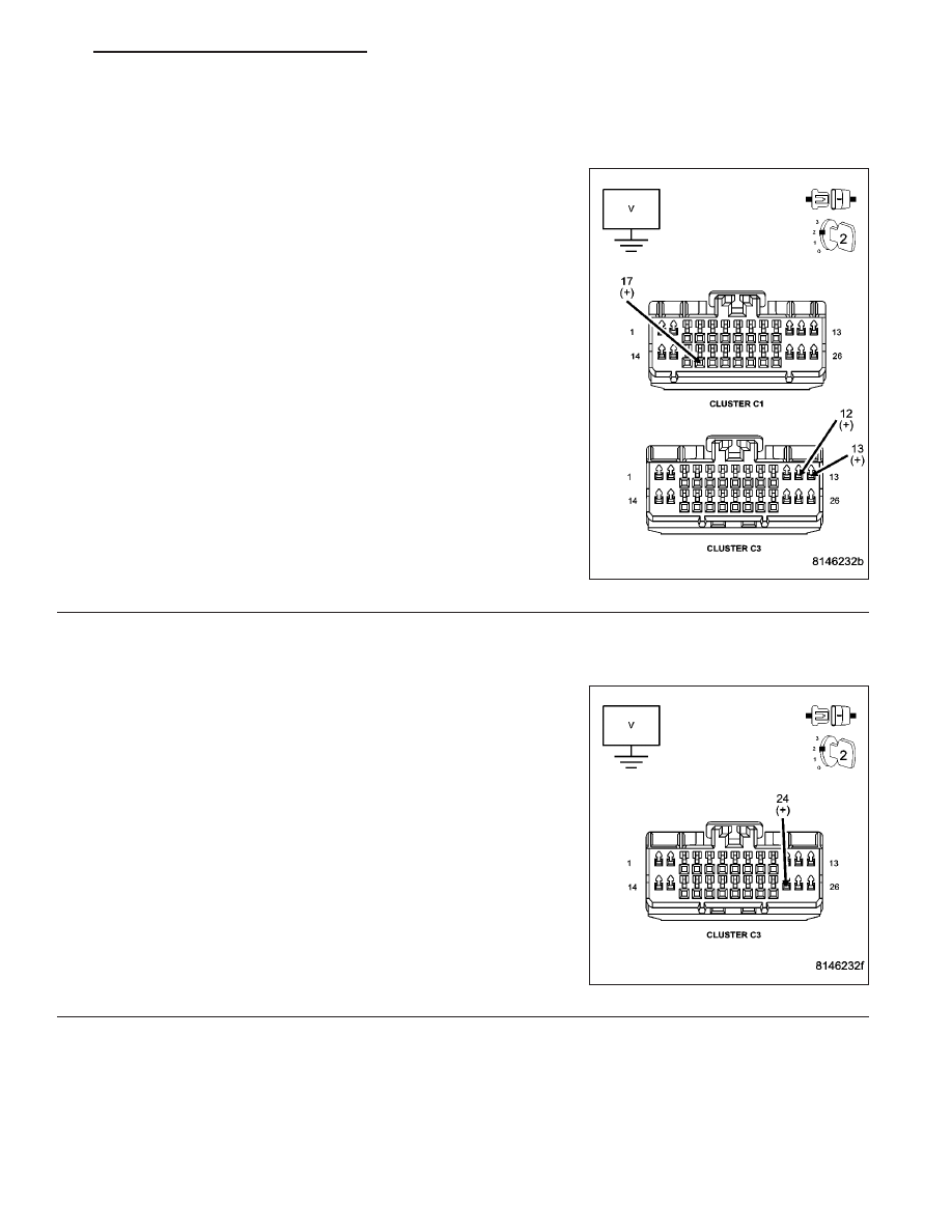
CHECK VOLTAGE OF THE IGNITION SWITCH OUTPUT CIRCUITS AT THE INSTRUMENT CLUSTER C1
AND C3 CONNECTORS

NOTE: Remove the starter relay.
Disconnect the Instrument Cluster C1 and C3 harness connectors.

Turn the ignition on.

Measure the voltage of the following circuits:

(F21) Ignition Switch Output (RUN/START) circuit with the ignition
in the RUN, and START positions.

(F1) Ignition Switch Output (UNLOCK/RUN/START) circuit with
the ignition in the RUN and START positions.

(F924) Ignition Switch Output (RUN) circuit with the ignition in the
RUN position.

Is the voltage above 10.0 volts on each circuit?

Yes

>> Go To 5

No

>> Go To 5

5.

CHECK VOLTAGE OF THE (F983) IGNITION SWITCH OUTPUT (RUN/ACC) CIRCUIT AT THE INSTRUMENT
CLUSTER C3 HARNESS CONNECTOR

NOTE: Reinstall the Starter Relay.
Measure the voltage of the (F983) Ignition Switch Output (RUN/ACC)
circuit.

Is the voltage above 10.0 volts on all the circuits tested in steps
4 and 5?

Yes

>> Replace the Instrument Cluster in accordance with the ser-

vice information.

Perform the BODY VERIFICATION TEST-VER 1.

No: (F21) (F924) or (F1) below 10.0 volts

Go To 6

No: (F983) below 10.0 volts

Go To 7

HB

INSTRUMENT CLUSTER - ELECTRICAL DIAGNOSTICS

8J - 13

B2107–IGNITION SWITCH SENSE INPUT CIRCUIT/PERFORMANCE (CONTINUED)

6.

CHECK THE IGNITION SWITCH OUTPUT CIRCUITS WITH VOLTAGE BELOW 10.0 VOLTS FOR AN OPEN

Turn the ignition off.

Disconnect the Ignition Switch harness connector.

Measure the resistance of the Ignition Switch Output circuit(s) (F21),
(F924), (F1) (from step 5, the circuit(s) below 10.0 volts) between the
Ignition Switch harness connector and the Instrument Cluster C1/C3
harness connector.

Is the resistance below 5.0 ohms?

Yes

>> Replace the Ignition Switch in accordance with the service

information.

Perform the BODY VERIFICATION TEST-VER 1. (Refer to
8 - ELECTRICAL/ELECTRONIC CONTROL MODULES/
FRONT CONTROL MODULE - DIAGNOSIS AND TEST-
ING)

No

>> Repair the circuit(s) with a resistance above 5.0 ohms.

Perform the BODY VERIFICATION TEST-VER 1. (Refer to
8 - ELECTRICAL/ELECTRONIC CONTROL MODULES/
FRONT CONTROL MODULE - DIAGNOSIS AND TEST-
ING)

7.

CHECK THE (F983) IGNITION SWITCH OUTPUT (RUN/ACC) CIRCUIT FOR AN OPEN

Turn the ignition off.

Disconnect the Ignition Switch harness connector.

Measure the resistance of the (F983) Ignition Switch Output (RUN/
ACC) circuit between the Ignition Switch harness connector and the
Instrument Cluster C3 harness connector.

Is the resistance below 5.0 ohms?

Yes

>> Go To 8

No

>> Repair the (F983) Ignition Switch Output (RUN/ACC) cir-

cuit for an open.

Perform the BODY VERIFICATION TEST-VER 1. (Refer to
8 - ELECTRICAL/ELECTRONIC CONTROL MODULES/
FRONT CONTROL MODULE - DIAGNOSIS AND TEST-
ING)

8J - 14

INSTRUMENT CLUSTER - ELECTRICAL DIAGNOSTICS

HB

B2107–IGNITION SWITCH SENSE INPUT CIRCUIT/PERFORMANCE (CONTINUED)

8.

CHECK VOLTAGE OF THE (A953) IGNITION (RUN/ACC) CIRCUIT AT THE IGNITION SWITCH HARNESS
CONNECTOR

Measure the voltage of the (A953) Ignition (RUN/ACC) circuit.

Is the voltage above 10.0 volts?

Yes

>> Replace the Ignition Switch in accordance with the service

information.

Perform the BODY VERIFICATION TEST-VER 1. (Refer to
8 - ELECTRICAL/ELECTRONIC CONTROL MODULES/
FRONT CONTROL MODULE - DIAGNOSIS AND TEST-
ING)

No

>> Repair the (A953) Ignition (RUN/ACC) circuit for an open.

Perform the BODY VERIFICATION TEST-VER 1. (Refer to
8 - ELECTRICAL/ELECTRONIC CONTROL MODULES/
FRONT CONTROL MODULE - DIAGNOSIS AND TEST-
ING)

9.

CHECK (F983) IGNITION SWITCH OUTPUT (RUN/ACC) CIRCUIT FOR A SHORT TO GROUND

Disconnect the Ignition Switch harness connector.

Disconnect the Instrument Cluster C3 harness connector.

Measure the resistance between ground and the (F983) Ignition
Switch Output (RUN/ACC) circuit at the Ignition Switch harness con-
nector.

Is the resistance below 10K ohms?

YES

>> Repair the (F983) Ignition Switch Output (RUN/ACC) cir-

cuit for a short to ground.

Perform the BODY VERIFICATION TEST-VER 1. (Refer to
8 - ELECTRICAL/ELECTRONIC CONTROL MODULES/
FRONT CONTROL MODULE - DIAGNOSIS AND TEST-
ING)

NO

>> Go To 10

HB

INSTRUMENT CLUSTER - ELECTRICAL DIAGNOSTICS

8J - 15

B2107–IGNITION SWITCH SENSE INPUT CIRCUIT/PERFORMANCE (CONTINUED)

10.

CHECK (A953) IGNITION SWITCH OUTPUT (RUN/ACC) CIRCUIT FOR A SHORT TO GROUND

Measure the resistance between ground and the (A953) Ignition
Switch Output (RUN/ACC) circuit at the Ignition Switch harness con-
nector.

Is the resistance below 10K ohms?

YES

>> Repair the (A953) Ignition Switch Output (RUN/ACC) cir-

cuit for a short to ground.

Perform the BODY VERIFICATION TEST-VER 1. (Refer to
8 - ELECTRICAL/ELECTRONIC CONTROL MODULES/
FRONT CONTROL MODULE - DIAGNOSIS AND TEST-
ING)

NO

>> Go To 11

11.

CHECK THE INSTRUMENT CLUSTER FOR A SHORT TO GROUND

Reconnect the Ignition Switch harness connector.

Replace PDC fuse #27 for the (A953) Ignition Switch Output (RUN/
ACC) circuit.

Cycle the ignition switch through all positions.

Turn the ignition off.

Check the PDC fuse #27 for the (A953) Ignition Switch Output (RUN/
ACC) circuit.

Is the fuse open?

YES

>> Replace the Ignition Switch in accordance with the service

information.

Perform the BODY VERIFICATION TEST-VER 1. (Refer to
8 - ELECTRICAL/ELECTRONIC CONTROL MODULES/
FRONT CONTROL MODULE - DIAGNOSIS AND TEST-
ING)

NO

>> Replace the Instrument Cluster in accordance with the ser-

vice information

Perform the BODY VERIFICATION TEST-VER 1. (Refer to
8 - ELECTRICAL/ELECTRONIC CONTROL MODULES/
FRONT CONTROL MODULE - DIAGNOSIS AND TEST-
ING)

8J - 16

INSTRUMENT CLUSTER - ELECTRICAL DIAGNOSTICS

HB


Content   ..  302  303  304  305   ..