Dodge Durango (HB). Manual - part 300


  Index      Dodge     Dodge Durango (HB) - service repair manual 2005 year


Search            


Content   ..  298  299  300  301   ..


Dodge Durango (HB). Manual - part 300


INSTALLATION

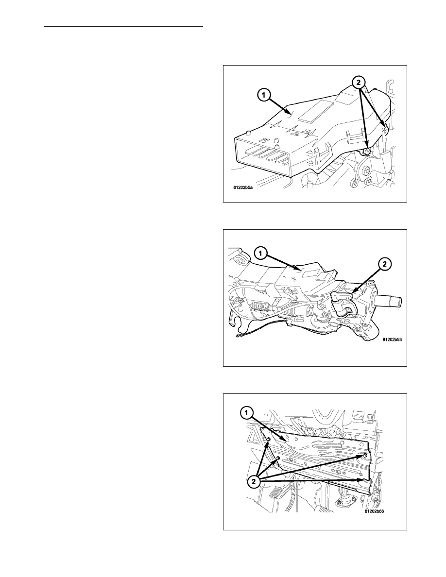
1. Before installing ignition switch (1), rotate the slot

in the switch to the ON position.

2. Connect the electrical connector to rear of the igni-

tion switch. Make sure that locking tabs are fully
seated into wiring connector.

3. Position switch to column and install the mounting

screws (2). Tighten screw to 3 N·m (26 in. lbs.).

4. Install the tilt lever bracket (2) mounting screws.

Tighten screws to 4.5 N·m (40 in. lbs.).

5. Position the wire retainer into the tilt lever bracket.

6. Reconnect the lower clockspring connectors.

7. Install the steering column opening reinforcement

(1).

HB

IGNITION SYSTEM - SERVICE INFORMATION

8I - 31

8. Install the steering column opening cover (2).

9. Install the key cylinder (1) with the key (2) in the

cylinder (1).

10. Install steering column upper and lower shrouds

(2).

11. Install the tilt lever knob (1).

12. Enable the airbag system. (Refer to 8 - ELECTRI-

CAL/RESTRAINTS/DRIVER

AIRBAG

-

INSTALLATION).

8I - 32

IGNITION SYSTEM - SERVICE INFORMATION

HB

SWITCH-KEY-IN IGNITION

DESCRIPTION

The key-in ignition switch is integral to the ignition switch, which is mounted on the left side of the steering column.
It closes a path to ground for the Central Timer Module (CTM) when the ignition key is inserted in the ignition key
cylinder and the driver door ajar switch is closed (driver door is open). The key-in ignition switch opens the ground
path when the key is removed from the ignition key cylinder. The ground path is also opened when the driver door
ajar switch is open (driver door is closed).

The key-in ignition switch cannot be repaired and, if faulty or damaged, the entire ignition switch must be replaced,
(Refer to 19 - STEERING/COLUMN/IGNITION SWITCH - REMOVAL).

DIAGNOSIS AND TESTING

IGNITION SWITCH AND KEY LOCK CYLINDER

ELECTRICAL DIAGNOSIS

For ignition switch electrical schematics, refer to the appropriate section in Wiring Diagrams.

MECHANICAL DIAGNOSIS (KEY DIFFICULT TO ROTATE)

Vehicles equipped with an automatic transmission and a steering column mounted shifter: an interlock
device is located within the steering column. This interlock device is used to lock the transmission shifter in the
PARK position when the key cylinder is in any position and the brake pedal is not depressed.

Vehicles equipped with a manual transmission and a floor mounted shifter: on certain models, a lever is
located on the steering column behind the ignition key cylinder. The lever must be manually operated to allow rota-
tion of the ignition key cylinder to any position. If it is difficult to rotate the key to any position, the lever mechanism
may be defective. This mechanism is not serviceable. If repair is necessary, the steering column assembly must be
replaced. (Refer to 19 - STEERING/COLUMN - REMOVAL).

HB

IGNITION SYSTEM - SERVICE INFORMATION

8I - 33


Content   ..  298  299  300  301   ..