Dodge Durango (HB). Manual - part 266


  Index      Dodge     Dodge Durango (HB) - service repair manual 2005 year


Search            


Content   ..  264  265  266  267   ..


Dodge Durango (HB). Manual - part 266


HEATED GLASS - SERVICE INFORMATION

TABLE OF CONTENTS

page

page

HEATED GLASS - SERVICE INFORMATION

DESCRIPTION

. . . . . . . . . . . . . . . . . . . . . . . . . 11

OPERATION

. . . . . . . . . . . . . . . . . . . . . . . . . . . 12

DIAGNOSIS AND TESTING

REAR WINDOW DEFOGGER SYSTEM

. . . . . 12

GRID-REAR WINDOW DEFOGGER

STANDARD PROCEDURE

GRID REPAIR PROCEDURE

. . . . . . . . . . . . . 13

RELAY-REAR WINDOW DEFOGGER

DESCRIPTION

. . . . . . . . . . . . . . . . . . . . . . . . . 14

OPERATION

. . . . . . . . . . . . . . . . . . . . . . . . . . . 15

REMOVAL

. . . . . . . . . . . . . . . . . . . . . . . . . . . . . 15

INSTALLATION

. . . . . . . . . . . . . . . . . . . . . . . . . 16

SWITCH-REAR WINDOW DEFOGGER

DESCRIPTION

. . . . . . . . . . . . . . . . . . . . . . . . . 16

OPERATION

. . . . . . . . . . . . . . . . . . . . . . . . . . . 16

HEATED GLASS - SERVICE INFORMATION

DESCRIPTION

CAUTION: Grid lines can be damaged or scraped off with sharp instruments. Care should be taken in clean-
ing glass or removing foreign materials, decals or stickers. Normal glass cleaning solvents or hot water
used with rags or toweling is recommended.

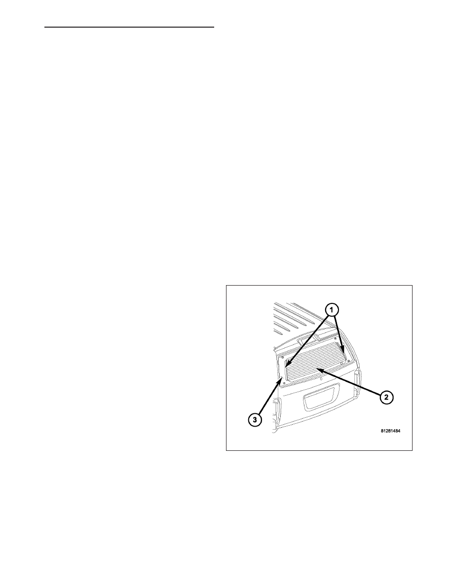
The rear window defogger system, also known as
electrical backlight (EBL), consists of two vertical bus
bars (1) linked by a series of grid lines (2) fired onto
the inside surface of the rear window (3).

The EBL system is turned ON or OFF by a control
switch located on the A/C-heater control at the center
of the instrument panel and by a rear window defog-
ger relay timing circuit integral to the front control
module (FCM) (Refer to 8 - ELECTRICAL/HEATED
GLASS/REAR

WINDOW

DEFOGGER

SWITCH

-

DESCRIPTION).

Circuit protection is provided by a fuse located in the
junction block (JB) and a fuse located in the power
distribution center (PDC).

HB

HEATED GLASS - SERVICE INFORMATION

8G - 11

OPERATION

The electric backlight (EBL) system is controlled by a
momentary switch (2) located in the A/C-heater control
(1) on the instrument panel. When the defogger switch
for the EBL system is pressed to the On position, cur-
rent is directed to the rear defogger grid lines and the
heated power mirrors (if equipped). The heated grid
lines heat the glass to help clear the rear window and
side mirror surfaces of fog or frost.

A yellow indicator (3) in the defogger switch will illu-
minate to indicate when the EBL system is turned on.
The front control module (FCM) contains the EBL sys-
tem control circuitry.

Note: The EBL system turns off automatically after
approximately 15 minutes of initial operation. Each
following activation cycle of the EBL system will
last approximately 10 minutes.

The EBL system will be automatically turned off after
a programmed time interval of about 15 minutes. After
the initial time interval has expired, if the defogger
switch is turned on again during the same ignition
cycle, the defogger system will automatically turn off
after about 10 minutes.

The EBL system will automatically shut off if the ignition switch is turned to the Off position, or it can be turned off
manually by depressing the defogger switch a second time.

DIAGNOSIS AND TESTING

REAR WINDOW DEFOGGER SYSTEM

Note: Illumination of the defogger switch indicator lamp means that there is electrical current available at
the output of the rear window defogger logic circuitry, but does not confirm that the electrical current is
reaching the rear glass heating grid lines.

Note: For circuit descriptions and diagrams of the rear window defogger system, refer to 8W - WIRING DIA-
GRAM INFORMATION.

Operation of the electrical backlight (EBL) system can be confirmed by the following:

8G - 12

HEATED GLASS - SERVICE INFORMATION

HB

1. Using a scan tool, check for diagnostic trouble

codes (DTCs) related to the A/C-heater control and
the front control module (FCM). If no DTCs are
found, go to Step 2. If any DTCs are found, repair
as required, then proceed to Step 2

2. Turn the ignition switch to the On position. Set the

defogger switch in the On position. The rear win-
dow defogger operation can be checked by feeling
the rear window or outside rear view mirror glass.
A distinct difference in temperature between the
grid lines (4 and 5) and the adjacent clear glass or
the mirror glass can be detected within three to
four minutes of operation.

3. If a temperature difference is not detected, use a

12-volt DC voltmeter and contact the rear glass
heating grid terminal A (1) with the negative lead,
and terminal B (2) with the positive lead. The volt-
meter should read battery voltage. If the voltmeter
does not read battery voltage, check the following:

Confirm that the ignition switch is in the On
position.

Make sure that the rear glass heating grid
feed wire (3) and ground wire (6) are con-
nected to the terminals. Confirm that the
ground wire has continuity to ground.

Check the EBL relay and fuse located in
the junction block (JB). The relay and
fuse must be tight in their receptacles
and all electrical connections must be
secure.

Check the fuse located in the power
distribution center (PDC). The fuse
must be tight in its receptacle and all
electrical connections must be secure.

When the above steps have been completed and the rear glass heating grid is still inoperative, one or more of the
following is faulty:

Rear window defogger control switch in the A/C-heater control.

Rear window defogger grid lines (all grid lines would have to be broken, or the power feed or the ground
wire disconnected, for the entire heating grid to be inoperative).

GRID-REAR WINDOW DEFOGGER

STANDARD PROCEDURE

GRID REPAIR PROCEDURE

WARNING: Materials contained in the Repair Kit (Part Number 04549275) may cause skin or eye irritation.
The kit contains epoxy resin and amine type hardener, which are harmful if swallowed. Avoid contact with
the skin and eyes. For skin contact, wash the affected areas with soap and water. For contact with the eyes,
flush with plenty of water. Do not take internally. If taken internally, induce vomiting and call a physician
immediately. Use with adequate ventilation. Do not use near fire or flame. Contains flammable solvents.
Keep out of the reach of children. Failure to follow the warnings could result in possible personal injury or
death.

HB

HEATED GLASS - SERVICE INFORMATION

8G - 13

Repair of the rear glass heating grid lines, bus bars, terminals or pigtail wires can be accomplished using the Mopar
Rear Window Defogger Repair Kit (Part Number 04549275) or equivalent.

1. Mask the repair area with masking tape (3) so that

the conductive epoxy can be applied neatly. Extend
the epoxy application onto the grid line (2) or the
bus bar on each side of the break (1).

2. Follow the instructions in the repair kit for preparing

the damaged area.

3. Remove the package separator clamp and mix the

two

conductive

epoxy

components

thoroughly

within the packaging. Fold the package in half and
cut the center corner to dispense the epoxy.

4. For grid line repairs, mask the area to be repaired

with masking tape or use a template.

5. Apply the epoxy through the slit in the masking

tape or template. Overlap both ends of the break
by at least 19 millimeters (0.75 inch).

6. For a terminal or pigtail wire replacement, mask the adjacent areas so the epoxy can be extended onto the

adjacent grid line as well as the bus bar. Apply a thin layer of epoxy to the area where the terminal or pigtail wire
was fastened and onto the adjacent grid line.

7. Apply a thin layer of conductive epoxy to the terminal or bare wire end of the pigtail and place it in the proper

location on the bus bar. To prevent the terminal or pigtail wire from moving while the epoxy is curing, it must be
wedged or clamped.

8. Carefully remove the masking tape or template.

CAUTION: Do not allow the glass surface to exceed 204° C (400° F) or the glass may fracture.

9. Allow the epoxy to cure 24 hours at room temperature, or use a heat gun with a 260° to 371° C (500° to 700°

F) range for fifteen minutes. Hold the heat gun approximately 25.4 centimeters (10 inches) from the repair.

10. After the conductive epoxy is properly cured, remove the wedge or clamp from the terminal or pigtail wire. Do

not attach the wire harness connectors until the curing process is complete.

11. Check the operation of the rear window defogger glass heating grid.

RELAY-REAR WINDOW DEFOGGER

DESCRIPTION

The rear window defogger (EBL) relay is a Interna-
tional Standards Organization (ISO)-type relay. Relays
conforming to the ISO specifications have common
physical dimensions, current capacities, terminal pat-
terns, and terminal functions. The EBL relay is a elec-
tromechanical device that switches battery current
through a fuse in the power distribution center (PDC)
to the rear window defogger grid and to the outside
mirror heating grids. The EBL relay is energized when
the relay coil is provided a ground path by the rear
window defogger relay control in the front control
module (FCM).

The EBL relay is located in the junction block (JB) in
the passenger compartment.

8G - 14

HEATED GLASS - SERVICE INFORMATION

HB


Content   ..  264  265  266  267   ..