Dodge Durango (HB). Manual - part 263
5.7L V-8
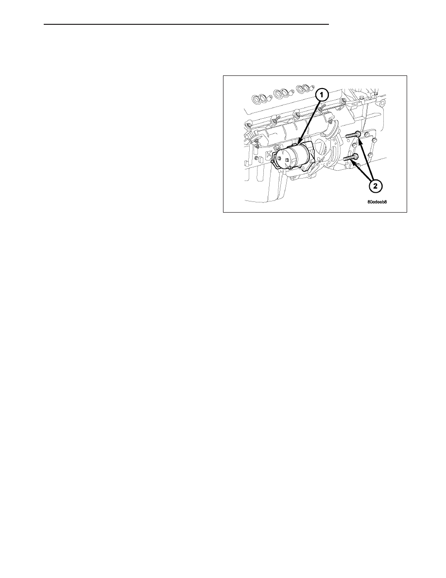
1. Connect solenoid wire to starter motor (snaps on).
2. Position battery cable to solenoid stud. Install and
tighten battery cable eyelet nut. Refer to Torque
Specifications. Do not allow starter motor to hang
from wire harness.
3. Position starter motor (1) to engine.
4. If equipped with automatic transmission, slide
cooler tube bracket into position.
5. Install and tighten both mounting bolts (2). Refer to
Torque Specifications.
6. Lower vehicle.
7. Connect negative battery cable.
RELAY-STARTER MOTOR
DESCRIPTION
The starter relay is an electromechanical device that switches battery current to the pull-in coil of the starter sole-
noid when the ignition switch is turned to the Start position. The starter relay is located in the Power Distribution
Center (PDC) in the engine compartment. See the PDC cover for relay identification and location.
The starter relay is a International Standards Organization (ISO) relay. Relays conforming to ISO specifications have
common physical dimensions, current capacities, terminal patterns, and terminal functions.
The starter relay cannot be repaired or adjusted. If faulty or damaged, it must be replaced.
OPERATION
The ISO relay consists of an electromagnetic coil, a resistor or diode, and three (two fixed and one movable) elec-
trical contacts. The movable (common feed) relay contact is held against one of the fixed contacts (normally closed)
by spring pressure. When electromagnetic coil is energized, it draws the movable contact away from normally
closed fixed contact, and holds it against the other (normally open) fixed contact.
When electromagnetic coil is de-energized, spring pressure returns movable contact to normally closed position. The
resistor or diode is connected in parallel with electromagnetic coil within relay, and helps to dissipate voltage spikes
produced when coil is de-energized.
REMOVAL
The starter relay is located in the Power Distribution Center (PDC). Refer to label on PDC cover for relay location.
1. Disconnect and isolate negative battery cable.
2. Remove cover from Power Distribution Center (PDC) for relay identification and location.
3. Remove starter relay from PDC.
4. Check condition of relay terminals and PDC connector terminals for damage or corrosion. Repair if necessary
before installing relay.
5. Check for pin height (pin height should be the same for all terminals within the PDC connector). Repair if nec-
essary before installing relay.
HB
STARTING
8F - 49