Dodge Durango (HB). Manual - part 249


  Index      Dodge     Dodge Durango (HB) - service repair manual 2005 year


Search            


Content   ..  247  248  249  250   ..


Dodge Durango (HB). Manual - part 249


TRANSFER CASE VERIFICATION TEST VER 1

Diagnostic Test

1.

TRANSFER CASE VERIFICATION TEST— VER 1

Disconnect all jumper wires and reconnect all previously disconnected components and connectors.

With the scan tool, Clear DTCs.

Make sure that all accessories are turned off and that the battery is fully charged.

Move the Transfer Case Selector Switch to the desired position.

Test drive the vehicle in each Transfer Case range and verify proper operation in each range.

NOTE: To select or deselect 2WD, AWD or 4HI mode, vehicle speed must be below 55 MPH (88 KM/H) with
all wheels at vehicle speed.

NOTE: Shifts will not take place with a wheel speed difference of greater than 13 MPH between the front and
rear wheels.

NOTE: To select or deselect 4LO (if equipped), vehicle speed must be below 3 MPH (5 KM/H) with the igni-
tion ON and the transmission in neutral (auto trans) or the clutch pedal pressed (man trans).

NOTE: To select or deselect Transfer Case Neutral, vehicle speed must be 0 MPH with the ignition ON,
engine OFF, the brake pedal applied, and the transmission in neutral (auto trans) or the clutch pedal
pressed (man trans). Press the Neutral button (if equipped) on the Transfer Case Selector Switch until the
Neutral Indicator is illuminated.

WARNING: Apply the parking brake. The vehicle may roll with the Transfer Case in neutral.

NOTE: To verify that the Transfer Case is in Neutral, shift the automatic transmission into reverse and
release the brake pedal for three seconds or shift the manual transmission into gear and slowly release the
clutch pedal. There should be no vehicle movement if the Transfer Case is in Neutral.
With the scan tool, read DTCs in the Front Control Module (FCM) and the Instrument Cluster Module (CCN).

Are there any Transfer Case DTCs present in the Front Control Module (FCM) or the Instrument Cluster
Module (CCN)?

Yes

>> Return to the symptom list and perform the appropriate diagnostic test.

No

>> Repair is complete.

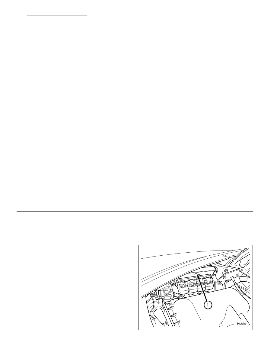
MODULE-TRANSMISSION CONTROL

DESCRIPTION

The Transmission Control Module (TCM) is a sub-
module within the Powertrain Control Module (PCM).
The PCM is located on the right inner fender.

HB

ELECTRONIC CONTROL MODULES - SERVICE INFORMATION

8E - 217

OPERATION

The Transmission Control Module (TCM) controls all electronic operations of the transmission. The TCM receives
information regarding vehicle operation from both direct and indirect inputs, and selects the operational mode of the
transmission. Direct inputs are hard wired to, and used specifically by the TCM. Indirect inputs are shared with the
TCM via the vehicle communication bus.

Some examples of direct inputs to the TCM are:

Battery (B+) voltage

Ignition “ON” voltage

Transmission Control Relay (Switched B+)

Throttle Position Sensor

Crankshaft Position Sensor

Transmission Range Sensor

Pressure Switches

Transmission Temperature Sensor

Input Shaft Speed Sensor

Output Shaft Speed Sensor

Line Pressure Sensor

Some examples of indirect inputs to the TCM are:

Engine/Body Identification

Manifold Pressure

Target Idle

Torque Reduction Confirmation

Engine Coolant Temperature

Ambient/Battery Temperature

Scan Tool Communication

Based on the information received from these various inputs, the TCM determines the appropriate shift schedule
and shift points, depending on the present operating conditions and driver demand. This is possible through the
control of various direct and indirect outputs.

Some examples of TCM direct outputs are:

Transmission Control Relay

Solenoids

Torque Reduction Request

Some examples of TCM indirect outputs are:

Transmission Temperature (to PCM)

PRNDL Position (to cluster/CCN)

In addition to monitoring inputs and controlling outputs, the TCM has other important responsibilities and functions:

Storing and maintaining Clutch Volume Indexes (CVI)

Storing and selecting appropriate Shift Schedules

System self-diagnostics

Diagnostic capabilities (with scan tool)

NOTE: If the TCM has been replaced, the “Quick Learn Procedure” must be performed. (Refer to 8 - ELEC-
TRICAL/ELECTRONIC CONTROL MODULES/TRANSMISSION CONTROL MODULE - STANDARD PROCE-
DURE)

BATTERY FEED

A fused, direct battery feed to the TCM is used for continuous power. This battery voltage is necessary to retain
memory in the TCM. When the battery (B+) is disconnected, this memory is lost. When the battery (B+) is restored,
this memory loss is detected by the TCM and a Diagnostic Trouble Code (DTC) is set.

8E - 218

ELECTRONIC CONTROL MODULES - SERVICE INFORMATION

HB

CLUTCH VOLUME INDEXES (CVI)

An important function of the TCM is to monitor Clutch
Volume Indexes (CVI). CVIs represent the volume of
fluid needed to compress a clutch pack.

The TCM monitors gear ratio changes by monitoring
the Input and Output Speed Sensors. The Input, or
Turbine Speed Sensor sends an electrical signal to
the TCM that represents input shaft rpm. The Output
Speed Sensor provides the TCM with output shaft
speed information.

By comparing the two inputs, the TCM can determine
transmission gear position. This is important to the
CVI calculation because the TCM determines CVIs by
monitoring how long it takes for a gear change to
occur.

Gear ratios can be determined by using the Scan Tool
and reading the Input/Output Speed Sensor values in
the “Monitors” display. Gear ratio can be obtained by
dividing the Input Speed Sensor value by the Output
Speed Sensor value.

For example, if the input shaft is rotating at 1000 rpm
and the output shaft is rotating at 500 rpm, then the
TCM can determine that the gear ratio is 2:1. In direct drive (3rd gear), the gear ratio changes to 1:1. The gear ratio
changes as clutches are applied and released. By monitoring the length of time it takes for the gear ratio to change
following a shift request, the TCM can determine the volume of fluid used to apply or release a friction element.

The volume of transmission fluid needed to apply the friction elements are continuously updated for adaptive con-
trols. As friction material wears, the volume of fluid need to apply the element increases.

Certain mechanical problems within the input clutch assembly can cause inadequate or out-of-range element vol-
umes. Also, defective Input/Output Speed Sensors and wiring can cause these conditions. The following charts iden-
tifies the appropriate clutch volumes and when they are monitored/updated:

42RLE

CLUTCH VOLUMES

Clutch

When Updated

Proper Clutch

Volume

Shift Sequence

Oil Temperature

Throttle Angle

L/R

2-1 or 3-1 coast

downshift

> 70°

< 5°

35 to 83

2/4

1-2 shift

> 110°

5 - 54°

20 to 77

OD

2-3 shift

48 to 150

UD

4-3 or 4-2 shift

> 5°

24 to 70

545RFE

CLUTCH VOLUMES

Clutch

When Updated

Proper Clutch Volume

L/R

2-1 or 3-1 downshift

45 to 134

2C

3-2 kickdown shift

25 to 85

OD

2-3 upshift

30 to 100

4C

3-4 upshift

30 to 85

UD

4-3 kickdown shift

30 to 100

HB

ELECTRONIC CONTROL MODULES - SERVICE INFORMATION

8E - 219

SHIFT SCHEDULES

As mentioned earlier, the TCM has programming that allows it to select a variety of shift schedules. Shift schedule
selection is dependent on the following:

Shift lever position

Throttle position

Engine load

Fluid temperature

Software level

As driving conditions change, the TCM appropriately adjusts the shift schedule. Refer to the following chart to deter-
mine the appropriate operation expected, depending on driving conditions.

Schedule

Condition

Expected Operation

Extreme Cold

Oil temperature below -16° F

-Park, Reverse, Neutral and 1st and
3rd gear only in D position, 2nd
gear only in Manual 2 or L

-No EMCC

Super Cold

Oil temperature between -12° F and
10° F

- Delayed 2-3 upshift

- Delayed 3-4 upshift

- Early 4-3 coastdown shift

- High speed 4-2, 3-2, 2-1 kickdown
shifts are prevented

-Shifts at high throttle openings willl
be early.

- No EMCC

Cold

Oil temperature between 10° F and
36° F

-Shift schedule is the same as
Super Cold except that the 2-3
upshifts are not delayed.

Warm

Oil temperature between 40° F and
80° F

- Normal operation (upshift,
kickdowns, and coastdowns)

- No EMCC

Hot

Oil temperature between 80° F and
240° F

- Normal operation (upshift,
kickdowns, and coastdowns)

- Normal EMCC operation

Overheat

Oil temperature above 240° F or
engine coolant temperature above
244° F

- Delayed 2-3 upshift

- Delayed 3-4 upshift

- 3rd gear FEMCC from 30-48 mph

- 3rd gear PEMCC above 35 mph

- Above 25 mph the torque
converter will not unlock unless the
throttle is closed or if a wide open
throttle 2nd PEMCC to 1 kickdown
is made

8E - 220

ELECTRONIC CONTROL MODULES - SERVICE INFORMATION

HB


Content   ..  247  248  249  250   ..