Dodge Durango (HB). Manual - part 1574


  Index      Dodge     Dodge Durango (HB) - service repair manual 2005 year


Search            


Content   ..  1572  1573  1574  1575   ..


Dodge Durango (HB). Manual - part 1574


4. Start the engine and allow it to idle. After the engine has reached normal operating temperature, allow the pas-

senger compartment to heat up. This will create the need for maximum refrigerant flow into the rear A/C evap-
orator.

5. If the refrigerant charge is sufficient, the discharge (high pressure) gauge should read 827 kPa to 1655 kPa (120

psi to 240 psi). The suction (low pressure) gauge should read 207 kPa to 345 kPa (30 psi to 50 psi). If OK, go
to Step 6. If not OK, replace the faulty rear A/C expansion valve.

WARNING:
Protect the skin and eyes from exposure to liquid CO

2

or personal injury can result.

6. If the suction (low pressure) gauge reads within the specified range, freeze the rear A/C expansion valve for 30

seconds using liquid CO

2

or another suitable super-cold material.Do not spray R-134a or R-12 refrigerant on

the rear A/C expansion valve for this test. The suction (low pressure) gauge reading should drop by 69 kPa
(10 psi). If OK, go to Step 7 If not OK, replace the faulty rear A/C expansion valve.

7. Allow the rear expansion valve control head to thaw. The suction (low pressure) gauge reading should stabilize

at 207 kPa to 345 kPa (30 psi to 50 psi). If not OK, replace the faulty rear A/C expansion valve.

8. When expansion valve testing is complete, test the overall A/C system performance (Refer to 24 - HEATING &

AIR CONDITIONING - DIAGNOSIS AND TESTING - A/C PERFORMANCE TEST).

REMOVAL

WARNING: Refer to the applicable warnings and cautions for this system before performing the following
operation (Refer to 24 - HEATING & AIR CONDITIONING/PLUMBING - FRONT - WARNINGS) and (Refer to 24
- HEATING & AIR CONDITIONING/PLUMBING - FRONT - CAUTIONS). Failure to follow the warnings and cau-
tions could result in possible personal injury or death.

1. Recover the refrigerant from the refrigerant system

(Refer to 24 - HEATING & AIR CONDITIONING/
PLUMBING - FRONT - STANDARD PROCEDURE
- REFRIGERANT SYSTEM RECOVERY).

2. Remove right rear quarter panel trim (Refer to 23 -

BODY/INTERIOR/QUARTER

PANEL

TRIM

-

REMOVAL).

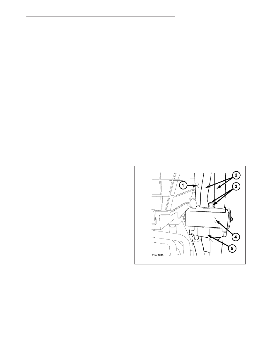
3. Remove the insulator (1) from around the rear A/C

evaporator tubes (2) to gain access the two rear
A/C expansion valve bolts (3).

4. Remove the two bolts that secure the rear A/C

expansion valve (4) between the rear A/C evapora-
tor tubes and the rear evaporator extension tube
tapping block (5).

5. Remove

the

rear A/C

expansion

valve

from

between the rear A/C evaporator tubes and the
rear evaporator extension tube tapping block and
remove and discard the O-ring seals.

6. Install plugs in, or tape over the opened evaporator tubes and extension tube fittings and all rear expansion valve

ports.

HB

PLUMBING - REAR

24 - 489

INSTALLATION

1. Remove the tape or plugs from the opened evapo-

rator tube and extension tube fittings and all rear
expansion valve ports.

2. Lubricate new rubber O-ring seals with clean refrig-

erant oil and install them on the evaporator tube
and extension tube fittings. Use only the specified
O-rings as they are made of a special material for
the R-134a system. Use only refrigerant oil of the
type recommended for the A/C compressor in the
vehicle.

3. Install the rear A/C expansion valve (4) between

the rear A/C evaporator tubes (2) and the rear
extension tube tapping block (5).

4. Install the two bolts (3) that secure the rear A/C

expansion valve between the rear A/C evaporator
tubes and the rear extension tube tapping block.
Tighten the bolts to 11 N·m (97 in. lbs.).

5. Install a new insulator (1) around the rear A/C

evaporator tubes.

6. Install the right rear quarter panel trim (Refer to 23 - BODY/INTERIOR/QUARTER PANEL TRIM - INSTALLA-

TION).

7. Evacuate the refrigerant system (Refer to 24 - HEATING & AIR CONDITIONING/PLUMBING - FRONT - STAN-

DARD PROCEDURE - REFRIGERANT SYSTEM EVACUATE).

8. Charge the refrigerant system (Refer to 24 - HEATING & AIR CONDITIONING/PLUMBING - FRONT - STAN-

DARD PROCEDURE - REFRIGERANT SYSTEM CHARGE).

24 - 490

PLUMBING - REAR

HB

EMISSIONS

TABLE OF CONTENTS

page

page

EMISSIONS

DESCRIPTION

STATE DISPLAY TEST MODE

. . . . . . . . . . . . . 1

CIRCUIT ACTUATION TEST MODE

. . . . . . . . . 1

DIAGNOSTIC TROUBLE CODES

. . . . . . . . . . . 1

TASK MANAGER

. . . . . . . . . . . . . . . . . . . . . . . 2

TRIP DEFINITION

. . . . . . . . . . . . . . . . . . . . . . 2

COMPONENT MONITORS

. . . . . . . . . . . . . . . . 2

OPERATION

TASK MANAGER

. . . . . . . . . . . . . . . . . . . . . . . 3

NON-MONITORED CIRCUITS

. . . . . . . . . . . . . 6

EVAPORATIVE EMISSIONS

. . . . . . . . . . . . . . . . . 8

EXHAUST GAS RECIRCULATION

. . . . . . . . . . . 26

EMISSIONS

DESCRIPTION

STATE DISPLAY TEST MODE

The switch inputs to the Powertrain Control Module (PCM) have two recognized states; HIGH and LOW. For this
reason, the PCM cannot recognize the difference between a selected switch position versus an open circuit, a short
circuit, or a defective switch. If the State Display screen shows the change from HIGH to LOW or LOW to HIGH,
assume the entire switch circuit to the PCM functions properly. Connect the DRB scan tool to the data link con-
nector and access the state display screen. Then access either State Display Inputs and Outputs or State Display
Sensors.

CIRCUIT ACTUATION TEST MODE

The Circuit Actuation Test Mode checks for proper operation of output circuits or devices the Powertrain Control
Module (PCM) may not internally recognize. The PCM attempts to activate these outputs and allow an observer to
verify proper operation. Most of the tests provide an audible or visual indication of device operation (click of relay
contacts, fuel spray, etc.). Except for intermittent conditions, if a device functions properly during testing, assume the
device, its associated wiring, and driver circuit work correctly. Connect a scan tool to the data link connector and
access the Actuators screen.

DIAGNOSTIC TROUBLE CODES

A Diagnostic Trouble Code (DTC) indicates the PCM has recognized an abnormal condition in the system.

Remember that DTC’s are the results of a system or circuit failure, but do not directly identify the failed
component or components.

BULB CHECK

Each time the ignition key is turned to the ON position, the malfunction indicator (check engine) lamp on the instru-
ment panel should illuminate for approximately 2 seconds then go out. This is done for a bulb check.

OBTAINING DTC’S USING A SCAN TOOL

1. Obtain the applicable Powertrain Diagnostic Manual.

2. Obtain a scan tool.

3. Connect the scan tool to the data link (diagnostic) connector. This connector is located in the passenger com-

partment; at the lower edge of instrument panel; near the steering column.

HB

EMISSIONS

25 - 1

4. Turn the ignition switch on and access the “Read Fault” screen.

5. Record all the DTC’s and “freeze frame” information shown on the scan tool.

6. To erase DTC’s, use the “Erase Trouble Code” data screen on the scan tool. Do not erase any DTC’s until

problems have been investigated and repairs have been performed.

TASK MANAGER

The PCM is responsible for efficiently coordinating the operation of all the emissions-related components. The PCM
is also responsible for determining if the diagnostic systems are operating properly. The software designed to carry
out these responsibilities is call the ’Task Manager’.

TRIP DEFINITION

The term “Trip” has different meanings depending on what the circumstances are. If the MIL (Malfunction Indicator
Lamp) is OFF, a Trip is defined as when the Oxygen Sensor Monitor and the Catalyst Monitor have been completed
in the same drive cycle.

When any Emission DTC is set, the MIL on the dash is turned ON. When the MIL is ON, it takes 3 good trips to turn
the MIL OFF. In this case, it depends on what type of DTC is set to know what a “Trip” is.

For the Fuel Monitor or Mis-Fire Monitor (continuous monitor), the vehicle must be operated in the “Similar Condition
Window” for a specified amount of time to be considered a Good Trip.

If a Non-Contiuous OBDII Monitor fails twice in a row and turns ON the MIL, re-running that monitor which previ-
ously failed, on the next start-up and passing the monitor, is considered to be a Good Trip. These will include the
following:

Oxygen Sensor

Catalyst Monitor

Purge Flow Monitor

Leak Detection Pump Monitor (if equipped)

EGR Monitor (if equipped)

Oxygen Sensor Heater Monitor

If any other Emission DTC is set (not an OBDII Monitor), a Good Trip is considered to be when the Oxygen Sensor
Monitor and Catalyst Monitor have been completed; or 2 Minutes of engine run time if the Oxygen Sensor Monitor
or Catalyst Monitor have been stopped from running.

It can take up to 2 Failures in a row to turn on the MIL. After the MIL is ON, it takes 3 Good Trips to turn the MIL
OFF. After the MIL is OFF, the PCM will self-erase the DTC after 40 Warm-up cycles. A Warm-up cycle is counted
when the ECT (Engine Coolant Temperature Sensor) has crossed 160°F and has risen by at least 40°F since the
engine has been started.

COMPONENT MONITORS

There are several components that will affect vehicle emissions if they malfunction. If one of these components
malfunctions the Malfunction Indicator Lamp (MIL) will illuminate.

Some of the component monitors are checking for proper operation of the part. Electrically operated components
now have input (rationality) and output (functionality) checks. Previously, a component like the Throttle Position sen-
sor (TPS) was checked by the PCM for an open or shorted circuit. If one of these conditions occurred, a DTC was
set. Now there is a check to ensure that the component is working. This is done by watching for a TPS indication
of a greater or lesser throttle opening than MAP and engine rpm indicate. In the case of the TPS, if engine vacuum
is high and engine rpm is 1600 or greater, and the TPS indicates a large throttle opening, a DTC will be set. The
same applies to low vacuum if the TPS indicates a small throttle opening.

All open/short circuit checks, or any component that has an associated limp-in, will set a fault after 1 trip with the
malfunction present. Components without an associated limp-in will take two trips to illuminate the MIL.

25 - 2

EMISSIONS

HB


Content   ..  1572  1573  1574  1575   ..