Dodge Durango (HB). Manual - part 1573


  Index      Dodge     Dodge Durango (HB) - service repair manual 2005 year


Search            


Content   ..  1571  1572  1573  1574   ..


Dodge Durango (HB). Manual - part 1573


22. Charge the refrigerant system (Refer to 24 - HEATING & AIR CONDITIONING/PLUMBING - FRONT - STAN-

DARD PROCEDURE - REFRIGERANT SYSTEM CHARGE).

PUMP-WATER-AUXILIARY

DESCRIPTION

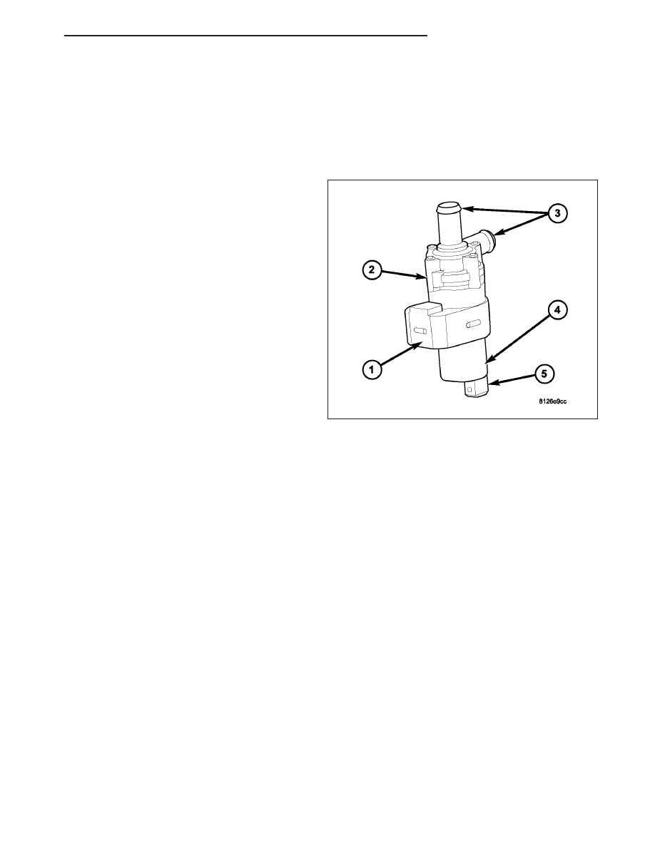
An electric auxiliary water pump is used on all models
to aid in circulating the engine coolant through the
front and rear heater core (depending on application).
The auxiliary water pump is mounted to the right front
frame rail by a rubber isolator (1) and consists of a
molded plastic housing (2) with two heater hose con-
nections (3), a 12 volt direct current (DC) motor and
impeller assembly (4) with an integral wire connector
receptacle (5).

OPERATION

The A/C-heater control operates the auxiliary water pump when all of the following conditions have been met.

Vehicle speed below 48 km/h (30 mph)

Coolant temperature between 10° C (50° F) and 110° C (230° F)

Front blower motor turned On

Rear temperature heat setting above the halfway setting (60% heat)

No fault conditions detected

The A/C-heater control turns the auxiliary water pump Off when any of the following conditions occur.

Vehicle speed above 48 km/h (30 mph)

Coolant temperature above 110° C (230° F)

Front blower motor turned Off

The auxiliary water pump cannot be adjusted or repaired and, if faulty or damaged, it must be replaced.

The auxiliary water pump is diagnosed using a scan tool. Refer to 24 - HVAC Electrical Diagnostics for more
information.

REMOVAL

CAUTION:
DO NOT apply excessive pressure on the auxiliary water pump tubes when removing the heater hoses.
Excessive pressure may damage the tubes, causing an engine coolant leak.

HB

PLUMBING - REAR

24 - 485

1. Disconnect and isolate the negative battery cable.

2. Drain the engine cooling system (Refer to 7 -

COOLING - STANDARD PROCEDURE - COOL-
ING SYSTEM DRAIN).

3. Remove the air cleaner housing from the right side

of the engine compartment (Refer to 9 - ENGINE/
AIR INTAKE SYSTEM/AIR CLEANER HOUSING -
REMOVAL).

4. Using spring tension clamp pliers, compress and

slide the hose clamps (1) off of the end of each
heater hose.

5. Disconnect each heater hose (2) by carefully twist-

ing the hose back and forth on the auxiliary water
pump tube (3), while gently pulling it off of the tube.

6. Remove the auxiliary water pump (1) from the

mounting bracket (2) located on the right front
frame rail (3).

7. Disconnect the wire harness connector (4) from the

auxiliary water pump and remove the pump from
the engine compartment.

24 - 486

PLUMBING - REAR

HB

INSTALLATION

1. Position the auxiliary water pum (1) into the engine

compartment and connect the wire harness con-
nector (4) to the pump.

2. Install the auxiliary water pum onto the mounting

bracket (2) located on the frame rail (3).

3. Using spring tension clamp pliers, compress and

slide the hose clamp (1) away from the end of the
heater hoses (2).

4. Install each heater hose by carefully twisting the

hose back and forth onto the auxiliary water pump
tubes (3), while gently pushing it onto the tube.

5. Using spring tension clamp pliers, compress and

slide the hose clamps onto the end of the heater
hoses.

6. Install the air cleaner housing to the right side of

the engine compartment (Refer to 9 - ENGINE/AIR
INTAKE

SYSTEM/AIR

CLEANER

HOUSING

-

REMOVAL).

7. Refill the engine cooling system (Refer to 7 -

COOLING - STANDARD PROCEDURE - COOL-
ING SYSTEM REFILL).

8. Reconnect the negative battery cable.

HB

PLUMBING - REAR

24 - 487

VALVE-A/C EXPANSION

DESCRIPTION

The rear A/C expansion valve is of a thermostatic
expansion

valve

(TXV)

design

and

controls

the

amount of refrigerant entering the rear A/C evaporator.
The rear A/C expansion valve consists of an aluminum
H-valve type body (1) with an integral thermal sensor
(2) and is located on the rear HVAC housing between
the rear evaporator extension tubes and the rear
evaporator.

OPERATION

The rear A/C expansion valve controls the high-pressure, low temperature liquid refrigerant from the rear liquid line
and converts it into a low-pressure, low-temperature mixture of liquid and gas before it enters the rear A/C evapo-
rator. A mechanical sensor in the rear A/C expansion valve monitors the temperature and pressure of the refrigerant
leaving the rear A/C evaporator through the rear suction line, and adjusts the orifice size at the rear liquid line port
to let the proper amount of refrigerant into the rear A/C evaporator to meet the vehicle A/C cooling requirements.
Controlling the refrigerant flow through the rear A/C evaporator ensures that none of the refrigerant leaving the rear
A/C evaporator is still in a liquid state, which could damage the A/C compressor.

The rear A/C expansion valve is factory calibrated and cannot be adjusted or repaired and, if faulty or damaged, it
must be replaced.

DIAGNOSIS AND TESTING

A/C EXPANSION VALVE - REAR

WARNING: Refer to the applicable warnings and cautions for this system before performing the following
operation (Refer to 24 - HEATING & AIR CONDITIONING/PLUMBING - FRONT - WARNINGS) and (Refer to 24
- HEATING & AIR CONDITIONING/PLUMBING - FRONT - CAUTIONS). Failure to follow the warnings and cau-
tions could result in possible personal injury.

NOTE: The rear A/C expansion valve should only be tested following testing of the A/C compressor.

NOTE: Liquid CO

2

is required to test the rear A/C expansion valve. This material is available from most

welding supply facilities. Liquid CO

2

is also available from companies which service and sell fire extinguish-

ers.

When testing the rear A/C expansion valve, the work area and the vehicle temperature must be 21° to 27° C (70°
to 85° F). To test the expansion valve:

1. Connect a charging station or manifold gauge set to the refrigerant system service ports. Verify the refrigerant

charge level.

2. Close all doors, windows and vents to the passenger compartment.

3. Set the A/C-heater controls for the rear heating-A/C system so that the A/C compressor is operating, the rear

temperature control is in the highest temperature position, and the blower motor is operating at the highest
speed.

24 - 488

PLUMBING - REAR

HB


Content   ..  1571  1572  1573  1574   ..