Content .. 1541 1542 1543 1544 ..
Dodge Durango (HB). Manual - part 1543
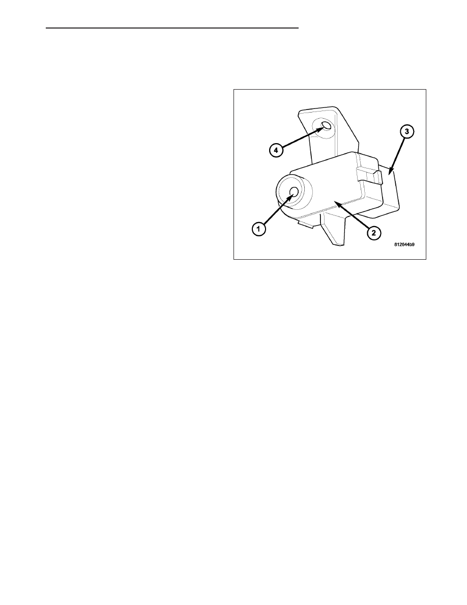
SENSOR-INFRARED
DESCRIPTION
The infrared sensor consists of an infrared transducer
(1) located on the driver side of the overhead console.
The infrared sensor is used only on models equipped
with the automatic temperature control (ATC) heater-
A/C system. The infrared transducer is contained
within a black molded plastic housing (2) with an inte-
gral wire connector receptacle (3). The integral mount-
ing tab (4) allows the infrared sensor to be secured
with one screw to the overhead console.
OPERATION
The infrared sensor detects thermal radiation emitted by the driver seat occupant and its surroundings and converts
its data into a linear pulse width modulated (PWM) output signal, which is sent to the compass temperature module
(EOM) through a two-wire lead and connector of the vehicle wire harness. The EOM sends a message over the
controller area network (CAN) B bus where it is read by the automatic temperature control (ATC) A/C-heater control.
The ATC A/C-heater control uses the infrared sensor data as one of the inputs necessary to automatically control
the interior cabin temperature level. By using thermal radiation (surface temperature) measurement, rather than an
air temperature measurement, the ATC heating-A/C system is able to adjust itself to the comfort level as perceived
by the occupant. This allows the ATC system to compensate for other ambient conditions affecting comfort levels,
such as solar heat gain or evaporative heat loss.
The ATC system logic responds to the infrared sensor message from the EOM by calculating and adjusting the air
flow temperature and air flow rate needed to properly obtain and maintain the selected comfort level temperature of
the occupants. The EOM continually monitors the infrared sensor circuits, and will store a diagnostic trouble code
(DTC) for any problem it detects.
The infrared sensor cannot be adjusted or repaired and, if faulty or damaged, it must be replaced.
The infrared sensor is diagnosed using a scan tool. Refer to 8 - Electrical Overhead Console Electrical Diagnostics
for more information.
HB
CONTROLS - FRONT
24 - 365