Content .. 1496 1497 1498 1499 ..
Dodge Durango (HB). Manual - part 1498
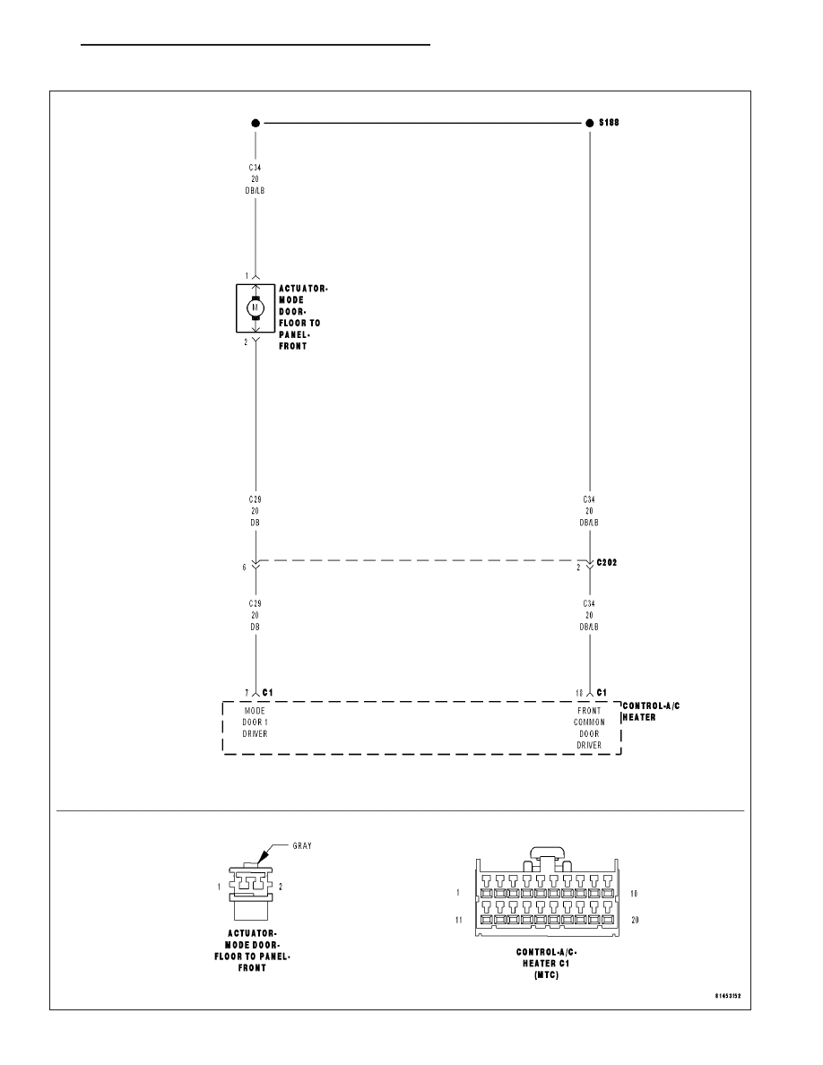
B1043–PANEL MODE DOOR 1 CONTROL CIRCUIT OPEN (MTC)
HB
HVAC - ELECTRICAL DIAGNOSTICS
24 - 185
|
|
|
Content .. 1496 1497 1498 1499 ..
B1043–PANEL MODE DOOR 1 CONTROL CIRCUIT OPEN (MTC) HB HVAC - ELECTRICAL DIAGNOSTICS 24 - 185 |