Dodge Durango (HB). Manual - part 1492


  Index      Dodge     Dodge Durango (HB) - service repair manual 2005 year


Search            


Content   ..  1490  1491  1492  1493   ..


Dodge Durango (HB). Manual - part 1492


B1032–EVAPORATOR FIN TEMPERATURE SENSOR CIRCUIT HIGH (MTC) (CONTINUED)

6.

CHECK (C121) SENSOR GROUND CIRCUIT FOR AN OPEN

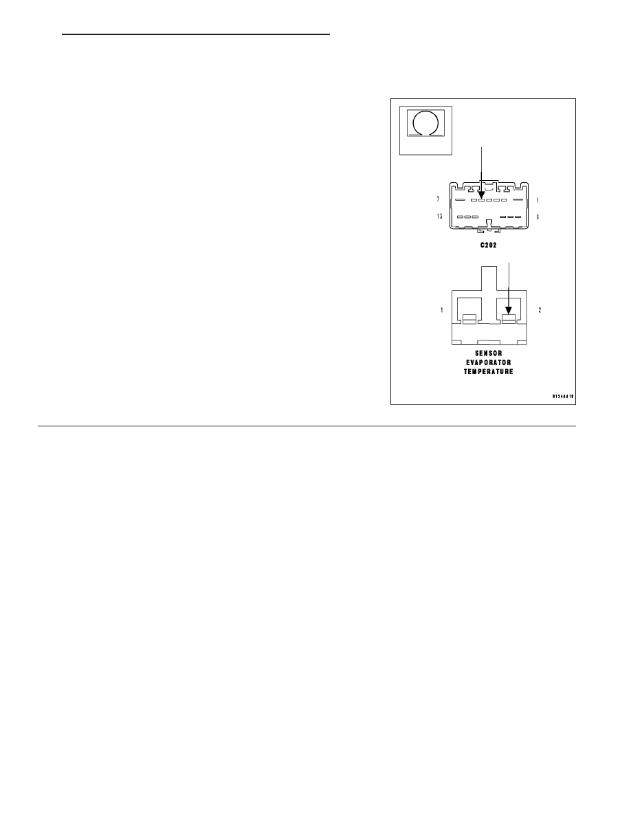
Measure the resistance of the (C121) Sensor Ground circuit between
the Evaporator Temperature Sensor harness connector and the in-line
C202 (HVAC SIDE) harness connector.

Is the resistance below 5.0 ohms?

Yes

>> Replace the Evaporator Temperature Sensor in accor-

dance with the Service Information.

Perform BODY VERIFICATION TEST - VER 1.

No

>> Repair the (C121) Sensor Ground circuit for an open

between the Evaporator Temperature Sensor harness con-
nector and the in-line C202 (HVAC SIDE) harness connec-
tor.

Perform BODY VERIFICATION TEST - VER 1.

HB

HVAC - ELECTRICAL DIAGNOSTICS

24 - 161

B1034–INFRARED TEMPERATURE SENSOR INPUT CIRCUIT LOW

For a complete wiring diagram Refer to Section 8W.

When Monitored:
With the ignition on.

Set Condition:
If the Compass Temperature Module (EOM) detects a short to ground on the (C38) Infrared Sensor Signal
circuit.

POSSIBLE CAUSES

(C83) INFRARED SENSOR SIGNAL CIRCUIT SHORTED TO GROUND

INFRARED TEMPERATURE SENSOR

COMPASS TEMPERATURE MODULE (EOM)

Theory of Operation

The A/C Heater Control requires IR Sensor data to function in an automatic mode. The IR Sensor is hard wired to
the Compass Temperature Module (EOM). The EOM broadcasts the IR Sensor data on the Controller Area Network
(CAN) B Bus where it is received and then processed by the A/C Heater Control.

Diagnostic Test

1.

PERFORM B1034–INFRARED TEMPERATURE SENSOR INPUT CIRCUIT LOW TEST

Repair

Perform test B1034–Infrared Temperature Sensor Input Circuit Low test. (Refer to 8 - ELECTRICAL/
OVERHEAD CONSOLE - DIAGNOSIS AND TESTING).

Perform BODY VERIFICATION TEST – VER 1.

24 - 162

HVAC - ELECTRICAL DIAGNOSTICS

HB

B1035–INFRARED TEMPERATURE SENSOR INPUT CIRCUIT HIGH

For a complete wiring diagram Refer to Section 8W.

When Monitored:
With the ignition on.

Set Condition:
If the Compass Temperature Module (EOM) detects a short high or open on the (C83) Infrared Sensor Signal
circuit.

POSSIBLE CAUSES

(C83) INFRARED SENSOR SIGNAL CIRCUIT SHORT TO VOLTAGE

(Z957) INFRARED SENSOR GROUND CIRCUIT OPEN

(C83) INFRARED SENSOR SIGNAL CIRCUIT OPEN

INFRARED TEMPERATURE SENSOR

COMPASS TEMPERATURE MODULE (EOM)

Theory of Operation

The A/C Heater Control requires IR Sensor data to function in an automatic mode. The IR Sensor is hard wired to
the Compass Temperature Module (EOM). The EOM broadcasts the IR Sensor data on the Controller Area Network
(CAN) B Bus where it is received and then processed by the A/C Heater Control.

Diagnostic Test

1.

PERFORM B1035–INFRARED TEMPERATURE SENSOR INPUT CIRCUIT HIGH TEST

Repair

Perform test B1035–Infrared Temperature Sensor Input Circuit High test. (Refer to 8 - ELECTRICAL/
OVERHEAD CONSOLE - DIAGNOSIS AND TESTING).

Perform BODY VERIFICATION TEST – VER 1.

HB

HVAC - ELECTRICAL DIAGNOSTICS

24 - 163

B1038–AUTO SWITCH REQUEST INPUT CIRCUIT LOW (ATC)

For a complete wiring diagram Refer to Section 8W.

When Monitored:
With the ignition on.

Set Condition:
If the Auto mode switch is stuck in a pushed position for more than two minutes. This DTC has a maturing
time of two minutes and a de-maturing time of two seconds. If the DTC’s status changes from active to stored
it will stay in memory for 100 ignition cycles.

Possible Causes

OBJECT HOLDING SWITCH IN A PUSHED POSITION

A/C HEATER CONTROL

Theory of Operation

The switch input changes when the switch is pushed down. An active DTC indicates that the switch is stuck in a
pushed position. A stored DTC indicates that the switch was stuck in a pushed position for more than two minutes,
but has since returned to its normal state.

NOTE: This DTC must be active for the results of this test to be valid. Do not perform this test if this DTC
is stored. Refer to HVAC System Test (ATC) for stored DTC test procedures.

Diagnostic Test

1.

INSPECT FOR OBJECT HOLDING SWITCH IN A PUSHED POSITION

Inspect the A/C Heater Control for an object holding the switch in a pushed position. If present, remove the object.

Turn the ignition on.

With the scan tool, erase HVAC DTCs.

Turn the ignition off, wait 10 seconds, and then turn the ignition on.

Wait two minutes, then with the scan tool, read HVAC DTCs.

Does the scan tool display active: B1038–AUTO SWITCH REQUEST INPUT CIRCUIT LOW?

Yes

>> Replace the A/C Heater Control in accordance with the Service Information.

Perform BODY VERIFICATION TEST – VER 1.

No

>> Perform BODY VERIFICATION TEST – VER 1.

24 - 164

HVAC - ELECTRICAL DIAGNOSTICS

HB


Content   ..  1490  1491  1492  1493   ..