Dodge Durango (HB). Manual - part 1490


  Index      Dodge     Dodge Durango (HB) - service repair manual 2005 year


Search            


Content   ..  1488  1489  1490  1491   ..


Dodge Durango (HB). Manual - part 1490


B1032–EVAPORATOR FIN TEMPERATURE SENSOR CIRCUIT HIGH (ATC) (CONTINUED)

For the Automatic Temperature Control (ATC) circuit diagram (Refer to 24 - HEATING & AIR CONDITIONING -
SCHEMATICS AND DIAGRAMS).

For a complete wiring diagram Refer to Section 8W.

When Monitored:
With the ignition on.

Set Condition:
If the Evaporator Temperature Sensor input is out of range toward the high voltage threshold, (A/D counts
reach high threshold of 240). This DTC has a maturing time of 5 seconds and a de-maturing time of 10 sec-
onds. If the DTC’s status changes from active to stored it will stay in memory for 100 ignition cycles.

Possible Causes

(C21) EVAPORATOR TEMPERATURE SENSOR SIGNAL CIRCUIT SHORTED TO VOLTAGE

(C21) EVAPORATOR TEMPERATURE SENSOR SIGNAL CIRCUIT OPEN

(C121) SENSOR GROUND CIRCUIT OPEN

EVAPORATOR TEMPERATURE SENSOR

A/C HEATER CONTROL

NOTE: This DTC must be active for the results of this test to be valid. Do not perform this test if this DTC
is stored. Refer to HVAC System Test (ATC) for stored DTC test procedures.

Diagnostic Test

1.

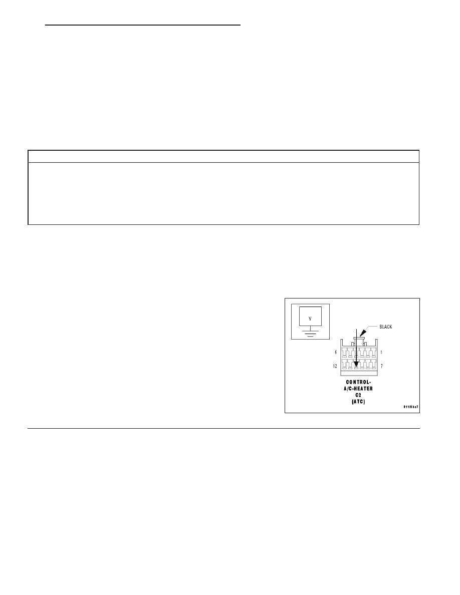
CHECK (C21) EVAPORATOR TEMPERATURE SENSOR SIGNAL CIRCUIT FOR A SHORT TO VOLTAGE

Turn the ignition off.

Disconnect the A/C Heater Control C2 harness connector.

Turn the ignition on.

Measure the voltage of the (C21) Evaporator Temperature Sensor Sig-
nal circuit.

Is the voltage above 0.2 volts?

Yes

>> Repair the (C21) Evaporator Temperature Sensor Signal

circuit for a short to voltage.

Perform BODY VERIFICATION TEST - VER 1.

No

>> Go To 2

HB

HVAC - ELECTRICAL DIAGNOSTICS

24 - 153

B1032–EVAPORATOR FIN TEMPERATURE SENSOR CIRCUIT HIGH (ATC) (CONTINUED)

2.

CHECK (C21) EVAPORATOR TEMPERATURE SENSOR SIGNAL CIRCUIT, (C121) SENSOR GROUND
CIRCUIT, & EVAPORATOR TEMPERATURE SENSOR

Turn the ignition off.

Measure the resistance between the (C21) Evaporator Temperature
Sensor Signal circuit and the (C121) Sensor Ground circuit in the A/C
Heater Control C2 harness connector. The approximate circuit resis-
tance should be as follows:

1468 ohms @ 40°C (104°F)

1800 ohms @ 35°C (95°F)

2221 ohms @ 30°C (86°F)

2757 ohms @ 25°C (77°F)

3443 ohms @ 20°C (68°F)

4330 ohms @ 15°C (59°F)

5485 ohms @ 10°C (50°F)

6998 ohms @ 5°C (41°F)

7354 ohms @ 4°C (39°F)

7731 ohms @ 3°C (37°F)

8130 ohms @ 2°C (36°F)

8553 ohms @ 1°C (34°F)

9000 ohms @ 0°C (32°F)

Is the resistance within the specifications?

Yes

>> Replace the A/C Heater Control in accordance with the Service Information.

Perform BODY VERIFICATION TEST - VER 1.

No

>> Go To 3

3.

CHECK (C21) EVAPORATOR TEMPERATURE SENSOR SIGNAL CIRCUIT FOR AN OPEN

Disconnect the in-line C202 harness connector.

Measure the resistance of the (C21) Evaporator Temperature Sensor
Signal circuit between the A/C Heater Control C2 harness connector
and the in-line C202 (IP SIDE) harness connector.

Is the resistance below 5.0 ohms?

Yes

>> Go To 4

No

>> Repair the (C21) Evaporator Temperature Sensor Signal

circuit for an open between the A/C Heater Control C2
harness connector and the in-line C202 (IP SIDE) harness
connector.

Perform BODY VERIFICATION TEST - VER 1.

24 - 154

HVAC - ELECTRICAL DIAGNOSTICS

HB

B1032–EVAPORATOR FIN TEMPERATURE SENSOR CIRCUIT HIGH (ATC) (CONTINUED)

4.

CHECK (C121) SENSOR GROUND CIRCUIT FOR AN OPEN

Measure the resistance of the (C121) Sensor Ground circuit between
the A/C Heater Control C2 harness connector and the in-line C202 (IP
SIDE) harness connector.

Is the resistance below 5.0 ohms?

Yes

>> Go To 5

No

>> Repair the (C121) Sensor Ground circuit for an open

between the A/C Heater Control C2 harness connector
and the in-line C202 (IP SIDE) harness connector.

Perform BODY VERIFICATION TEST - VER 1.

HB

HVAC - ELECTRICAL DIAGNOSTICS

24 - 155

B1032–EVAPORATOR FIN TEMPERATURE SENSOR CIRCUIT HIGH (ATC) (CONTINUED)

5.

CHECK (C21) EVAPORATOR TEMPERATURE SENSOR SIGNAL CIRCUIT FOR AN OPEN

Disconnect the Evaporator Temperature Sensor harness connector.

Measure the resistance of the (C21) Evaporator Temperature Sensor
Signal circuit between the Evaporator Temperature Sensor harness
connector and the in-line C202 (HVAC SIDE) harness connector.

Is the resistance below 5.0 ohms?

Yes

>> Go To 6

No

>> Repair the (C21) Evaporator Temperature Sensor Signal

circuit for an open between the Evaporator Temperature
Sensor harness connector and the in-line C202 (HVAC
SIDE) harness connector.

Perform BODY VERIFICATION TEST - VER 1.

6.

CHECK (C121) SENSOR GROUND CIRCUIT FOR AN OPEN

Measure the resistance of the (C121) Sensor Ground circuit between
the Evaporator Temperature Sensor harness connector and the in-line
C202 (HVAC SIDE) harness connector.

Is the resistance below 5.0 ohms?

Yes

>> Replace the Evaporator Temperature Sensor in accor-

dance with the Service Information.

Perform BODY VERIFICATION TEST - VER 1.

No

>> Repair the (C121) Sensor Ground circuit for an open

between the Evaporator Temperature Sensor harness con-
nector and the in-line C202 (HVAC SIDE) harness connec-
tor.

Perform BODY VERIFICATION TEST - VER 1.

24 - 156

HVAC - ELECTRICAL DIAGNOSTICS

HB


Content   ..  1488  1489  1490  1491   ..