Content .. 1386 1387 1388 1389 ..
Dodge Durango (HB). Manual - part 1388
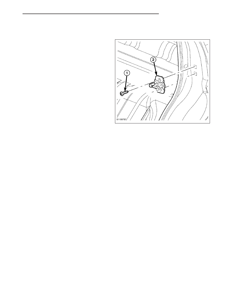
ADJUSTMENTS
ADJUSTMENT
1. Using a grease pencil or equivalent, mark the posi-
tion of the striker (2) to aid in adjustment.
2. Loosen the striker bolts (1).
3. Change the striker position to adjust the rear gap
and flush measurement. (Refer to 23 - BODY/
BODY STRUCTURE/GAP AND FLUSH - SPECIFI-
CATIONS)
4. Tighten the bolts to 28 N·m (21 ft. lbs.).
HB
DOORS - REAR
23 - 65