Dodge Durango (HB). Manual - part 1377


  Index      Dodge     Dodge Durango (HB) - service repair manual 2005 year


Search            


Content   ..  1375  1376  1377  1378   ..


Dodge Durango (HB). Manual - part 1377


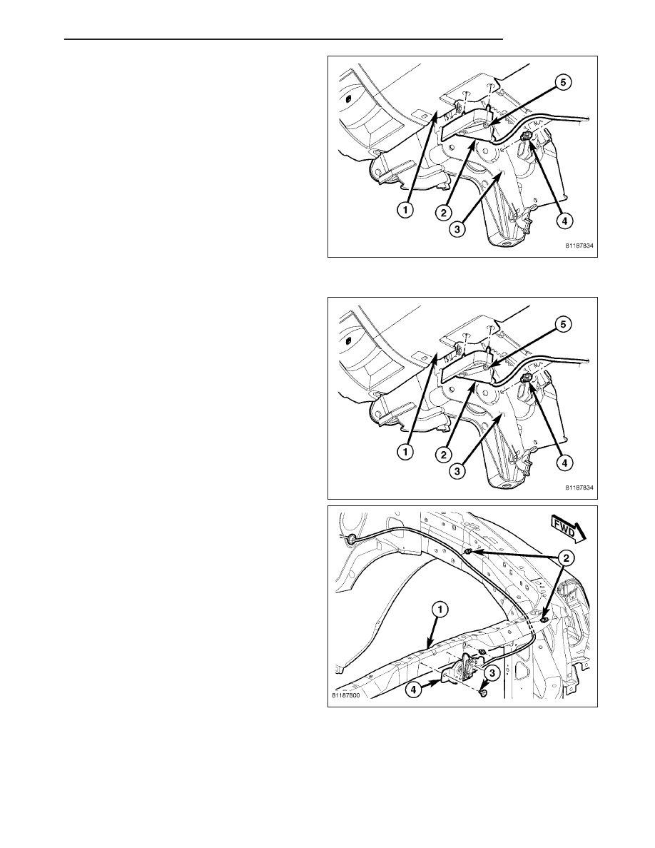
6. Separate the release cable grommet from the dash

panel hole.

7. Detach the release cable and the retainer clips (4).

8. From the inside of the vehicle, remove the screws

(5) attaching the hood release handle (2) to the
bottom of the instrument panel (1).

9. Pull/route the hood release cable through the dash

panel hole and remove it from the inside of the
vehicle.

INSTALLATION

NOTE: If replacement hood latch is also being
installed, ensure that it is thoroughly lubricated.

1. From inside the vehicle, pull/route the hood release

cable through the dash panel hole and into the
engine compartment.

2. Install the hood release handle (2) and install the

screws (5).

3. Install the cable grommet in the dash panel hole.

4. Attach the retainer clip (4) to the release cable and

install.

5. Attach the retainer clips (2) to the release cable

and install them into the holes in the engine com-
partment.

6. Install hood latch. (Refer to 23 - BODY/HOOD/

LATCH - INSTALLATION)

7. Install the wheelhouse splash shield and install the rivets. (Refer to 23 - BODY/EXTERIOR/FRONT WHEEL-

HOUSE SPLASH SHIELD - DESCRIPTION)

8. Install the left headlamp unit. (Refer to 8 - ELECTRICAL/LAMPS/LIGHTING - EXTERIOR/HEADLAMP UNIT -

INSTALLATION)

9. Install the grille. (Refer to 23 - BODY/EXTERIOR/GRILLE - INSTALLATION)

HB

HOOD

23 - 21

DOOR - FRONT

TABLE OF CONTENTS

page

page

PANEL-TRIM

REMOVAL

. . . . . . . . . . . . . . . . . . . . . . . . . . . . . 22

INSTALLATION

. . . . . . . . . . . . . . . . . . . . . . . . . 23

WATERSHIELD

REMOVAL

. . . . . . . . . . . . . . . . . . . . . . . . . . . . . 24

INSTALLATION

. . . . . . . . . . . . . . . . . . . . . . . . . 24

GLASS

REMOVAL

. . . . . . . . . . . . . . . . . . . . . . . . . . . . . 25

INSTALLATION

. . . . . . . . . . . . . . . . . . . . . . . . . 25

REGULATOR-WINDOW

REMOVAL

. . . . . . . . . . . . . . . . . . . . . . . . . . . . . 26

INSTALLATION

. . . . . . . . . . . . . . . . . . . . . . . . . 27

HANDLE-EXTERIOR

REMOVAL

. . . . . . . . . . . . . . . . . . . . . . . . . . . . . 28

INSTALLATION

. . . . . . . . . . . . . . . . . . . . . . . . . 29

CYLINDER-LOCK

REMOVAL

. . . . . . . . . . . . . . . . . . . . . . . . . . . . . 30

INSTALLATION

. . . . . . . . . . . . . . . . . . . . . . . . . 31

CHANNEL-GLASS

REMOVAL

. . . . . . . . . . . . . . . . . . . . . . . . . . . . . 31

INSTALLATION

. . . . . . . . . . . . . . . . . . . . . . . . . 32

LATCH

REMOVAL

. . . . . . . . . . . . . . . . . . . . . . . . . . . . . 33

INSTALLATION

. . . . . . . . . . . . . . . . . . . . . . . . . 34

ADJUSTMENTS

ADJUSTMENT

. . . . . . . . . . . . . . . . . . . . . . . . 35

DOOR

REMOVAL

. . . . . . . . . . . . . . . . . . . . . . . . . . . . . 35

INSTALLATION

. . . . . . . . . . . . . . . . . . . . . . . . . 36

ADJUSTMENTS

. . . . . . . . . . . . . . . . . . . . . . . . 36

HINGE

REMOVAL

. . . . . . . . . . . . . . . . . . . . . . . . . . . . . 41

INSTALLATION

. . . . . . . . . . . . . . . . . . . . . . . . . 41

STRIKER

REMOVAL

. . . . . . . . . . . . . . . . . . . . . . . . . . . . . 42

INSTALLATION

. . . . . . . . . . . . . . . . . . . . . . . . . 42

ADJUSTMENTS

ADJUSTMENT

. . . . . . . . . . . . . . . . . . . . . . . . 43

PANEL-TRIM

REMOVAL

1. Remove the screws (5 & 7).

CAUTION: Trim panel is attached to the door using
hooks molded into the panel. Do not pull the trim
panel straight off or damage to the panel and/or
power switch assembly may occur.

2. Lift the trim panel up off the lock rod (4) and

attachment hooks and separate the panel from the
door slightly.

3. Disconnect the electrical connectors (1).

4. Disconnect the inside handle actuator rod (3) and

remove the trim panel (6).

23 - 22

DOOR - FRONT

HB

5. Remove the switch panel (1) if necessary.

INSTALLATION

1. Install the switch assembly (1).

2. Position the trim panel (6) and connect the inside

handle actuator rod (3).

3. Connect the electrical connectors (1).

4. Lift the trim panel up and onto the lock rod (4) and

attachment hooks.

5. Install the screws (5 & 7).

HB

DOOR - FRONT

23 - 23

WATERSHIELD

REMOVAL

CAUTION: Do not allow the watershield or adhe-
sive to become contaminated with dirt or other
foreign substances.

Do not damage the watershield during removal
and installation.

If the watershield becomes contaminated or dam-
aged, replace the watershield.

1. Remove the speaker. (Refer to 8 - ELECTRICAL/

AUDIO/SPEAKER - REMOVAL)

2. Remove the door trim panel. (Refer to 23 - BODY/

DOOR - FRONT/TRIM PANEL - REMOVAL)

3. Separate the watershield (1) from the inner door

panel (2) and off of the latch linkages.

INSTALLATION

CAUTION: Do not allow the watershield or adhe-
sive to become contaminated with dirt or other
foreign substances.

Do not damage the watershield during removal
and installation.

If the watershield becomes contaminated or dam-
aged, replace the watershield.

1. Position

the

wire

harness

and

actuator

rods

through the holes in the watershield.

2. Secure the watershield to the inner door panel.

3. Install the speaker. (Refer to 8 - ELECTRICAL/AU-

DIO/SPEAKER - INSTALLATION)

4. Install the trim panel. (Refer to 23 - BODY/DOOR -

FRONT/TRIM PANEL - INSTALLATION)

23 - 24

DOOR - FRONT

HB


Content   ..  1375  1376  1377  1378   ..