Dodge Durango (HB). Manual - part 137
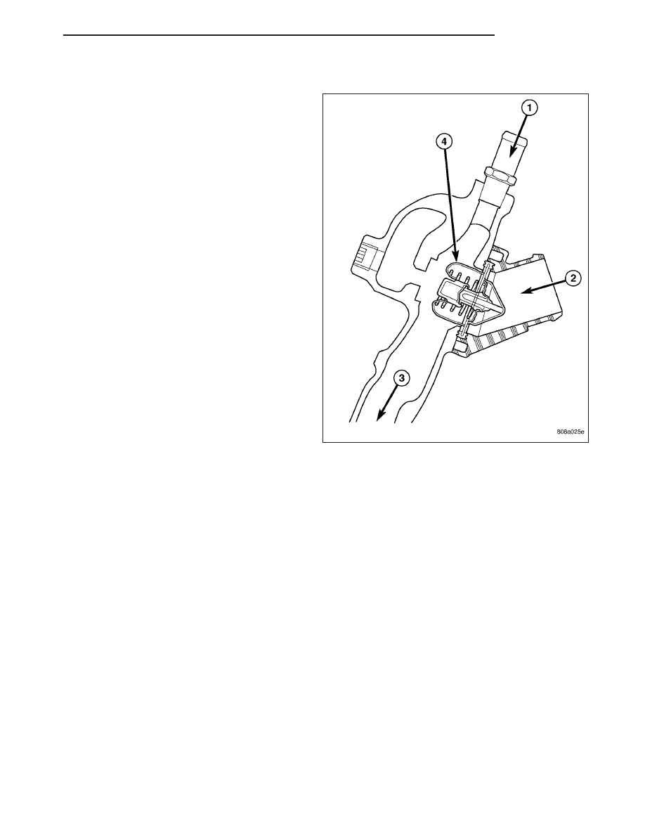
WATER PUMP BYPASS - 4.7L
The 4.7L engine uses an internal water/coolant bypass
system. The design uses galleries in the timing chain
cover to circulate coolant during engine warm-up pre-
venting the coolant from flowing through the radiator.
The thermostat (4) uses a stub shaft located at the
rear of the thermostat to control flow through the
bypass gallery.
OPERATION
WATER PUMP
A centrifugal water pump circulates coolant through the water jackets, passages, intake manifold, radiator core, cool-
ing system hoses and heater core, this coolant absorbs the heat generated when the engine is running. The pump
is driven by the engine crankshaft via a drive belt.
WATER PUMP BYPASS - 4.7L ENGINE
When the thermostat is in the closed position the bypass gallery is not obstructed allowing 100% flow. When the
thermostat is in the open position the pill partially covers the bypass hole, reducing the amount of bypass flow. This
design allows the coolant to reach operating temperature quickly when cold, while adding extra cooling during nor-
mal temperature operation.
REMOVAL
3.7L/4.7L ENGINE
The water pump on 3.7L/4.7L engines is bolted directly
to the engine timing chain case cover.
1. Disconnect negative battery cable.
2. Drain cooling system (Refer to 7 - COOLING -
STANDARD PROCEDURE).
HB
ENGINE
7 - 43