Dodge Durango (HB). Manual - part 135


  Index      Dodge     Dodge Durango (HB) - service repair manual 2005 year


Search            


Content   ..  133  134  135  136   ..


Dodge Durango (HB). Manual - part 135


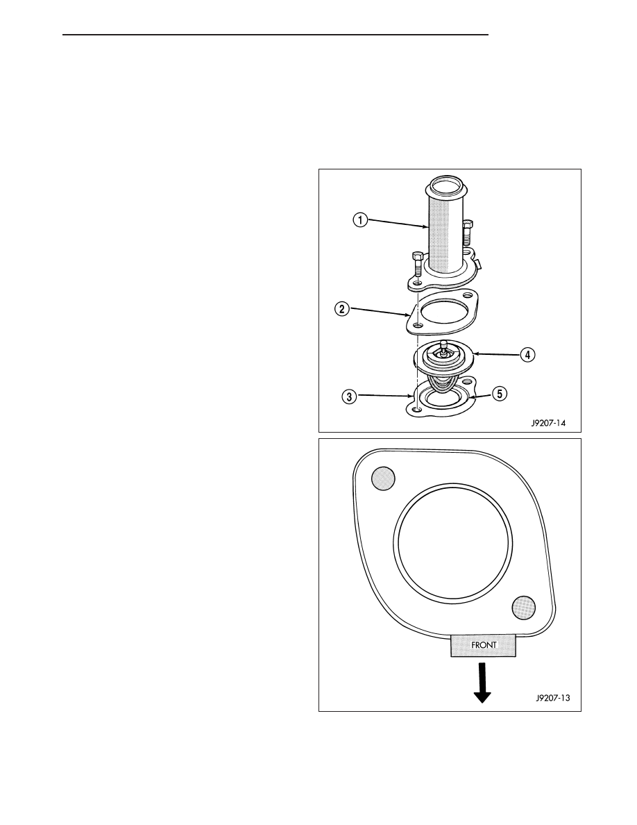
6. Remove thermostat housing mounting bolts , ther-

mostat housing (1) and thermostat (3).

INSTALLATION

5.7L ENGINE

1. Clean the mating areas of the intake manifold and

thermostat housing (1).

2. Install the thermostat (4) (spring side down) into the

recessed machined groove on the intake manifold.

3. Install the gasket on the intake manifold and over

the thermostat.

4. Position the thermostat housing (1) to the intake

manifold. Note: The word FRONT stamped on
housing. For adequate clearance, this must be
placed towards the front of the vehicle. The hous-
ing is slightly angled forward after the installation to
the intake manifold.

5. Install the housing-to-intake manifold bolts. Tighten

the bolts to 23 N·m (200 in. lbs.)

.

6. Install the radiator upper hose to the thermostat

housing.

7. Air Conditioned vehicles; Install the generator.

Tighten the bolts to 41 N·m (30 ft. lbs.).

8. Install the support bracket (generator mounting

bracket-to-intake manifold).. Tighten the bolts to 54
N·m (40 ft. lbs.).

9. Install the accessory drive belt (Refer to 7 - COOL-

ING/ACCESSORY DRIVE/DRIVE BELTS - INSTAL-
LATION).

10. Fill the cooling system (Refer to 7 - COOLING -

STANDARD PROCEDURE).

11. Connect battery negative cable.

12. Start and warm the engine. Check for leaks.

3.7L/4.7L ENGINE

1. Clean mating areas of timing chain cover and ther-

mostat housing.

2. Install thermostat (spring side down) into recessed

machined groove on timing chain cover.

3. Position thermostat housing on timing chain cover.

4. Install two housing-to-timing chain cover bolts.

Tighten bolts to 13 N·m (112 in. lbs.) torque.

HB

ENGINE

7 - 35

CAUTION: Housing must be tightened evenly and
thermostat must be centered into recessed groove
in timimg chain cover. If not, it may result in a
cracked housing, damaged timing chain cover
threads or coolant leaks.

5. Install lower radiator hose on thermostat housing.

6. Install splash shield.

7. Lower vehicle.

8. Fill cooling system (Refer to 7 - COOLING - STAN-

DARD PROCEDURE).

9. Connect negative battery cable to battery.

10. Start and warm the engine. Check for leaks.

RADIATOR

DESCRIPTION

The radiator (1) is a aluminum cross-flow design with
horizontal tubes through the radiator core and vertical
plastic side tanks.

OPERATION

The radiator supplies sufficient heat transfer using the cooling fins interlaced between the horizontal tubes in the
radiator core to cool the engine.

DIAGNOSIS AND TESTING

RADIATOR COOLANT FLOW

Use the following procedure to determine if coolant is flowing through cooling system.

1. Idle engine until operating temperature is reached. If upper radiator hose is warm to the touch, thermostat is

opening and coolant is flowing to radiator.

WARNING: HOT, PRESSURIZED COOLANT CAN CAUSE INJURY BY SCALDING. USING A RAG TO COVER
RADIATOR PRESSURE CAP, OPEN RADIATOR CAP SLOWLY TO FIRST STOP. ALLOW ANY BUILT-UP PRES-
SURE TO VENT TO THE RESERVE/OVERFLOW TANK. AFTER PRESSURE BUILD-UP HAS BEEN RELEASED,
REMOVE CAP FROM FILLER NECK.

2. Drain a small amount of coolant from radiator until ends of radiator tubes are visible through filler neck. Idle

engine at normal operating temperature. If coolant is flowing past exposed tubes, coolant is circulating.

7 - 36

ENGINE

HB

REMOVAL

1. Disconnect battery negative cable.

2. Drain cooling system (Refer to 7 - COOLING -

STANDARD PROCEDURE)

3. Remove pushpins (1) and the upper condenser/ra-

diator seal (2).

4. Remove air filer housing assembly.(Refer to 9 -

ENGINE/AIR

INTAKE

SYSTEM/AIR

CLEANER

ELEMENT - REMOVAL).

5. Remove upper radiator hose (1).

6. Remove overflow tube (2).

7. Remove radiator fan shroud (4) from the radiator

and position over the radiator fan.

8. Remove the upper radiator support (3).

9. Raise vehicle.

HB

ENGINE

7 - 37

10. Disconnect the power steering cooler lines (2).

11. Disconnect the transmission cooler lines (1).

12. Remove the lower radiator hose (2).

13. Lower vehicle.

14. Remove upper radiator mount.

15. Remove LH and RH radiator side seals.

16. Remove radiator.

17. Remove power steering cooler form the radiator, if

necessary.

18. Remove transmission cooler from radiator, if

necessary.

CLEANING

Clean radiator fins With the engine cold, apply cold water and compressed air to the back (engine side) of the
radiator to flush the radiator and/or A/C condenser of debris.

INSPECTION

The radiator cooling fins should be checked for damage or deterioration. Inspect cooling fins to make sure they are
not bent or crushed, these areas result in reduced heat exchange causing the cooling system to operate at higher
temperatures. Inspect the plastic end tanks for cracks, damage or leaks.

Inspect the radiator neck for damage or distortion.

7 - 38

ENGINE

HB


Content   ..  133  134  135  136   ..