Content .. 1353 1354 1355 1356 ..
Dodge Durango (HB). Manual - part 1355
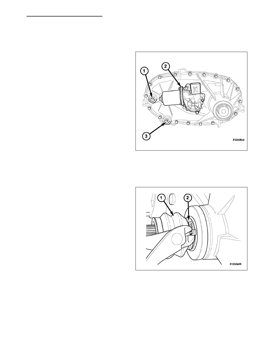
FLUID
STANDARD PROCEDURE - FLUID DRAIN AND REFILL
The fill and drain plugs (1, 3) are both in the rear
case.
1. Raise vehicle.
2. Position drain pan under transfer case.
3. Remove drain (3) and fill plugs (1) and drain lubri-
cant completely.
4. Install drain plug (3). Tighten plug to 20-34 N·m
(15-25 ft.lbs.).
5. Remove drain pan.
6. Fill transfer case to bottom edge of fill plug opening
with Mopar
T
ATF +4, Automatic Transmission fluid.
7. Install and tighten fill plug (1) to 20-34 N·m (15-25
ft.lbs.).
8. Lower vehicle.
SEAL-FRONT OUTPUT SHAFT
REMOVAL
1. Remove the front propeller shaft (Refer to 3 - DIF-
FERENTIAL & DRIVELINE/PROPELLER SHAFT/
PROPELLER SHAFT - REMOVAL).
2. Remove the front propeller shaft seal boot (1)
retaining clamp (2).
HB
TRANSFER CASE - NV144 - SERVICE INFORMATION
21 - 825