Dodge Durango (HB). Manual - part 1266


  Index      Dodge     Dodge Durango (HB) - service repair manual 2005 year


Search            


Content   ..  1264  1265  1266  1267   ..


Dodge Durango (HB). Manual - part 1266


P0846-2C PRESSURE SWITCH RATIONALITY (CONTINUED)

13.

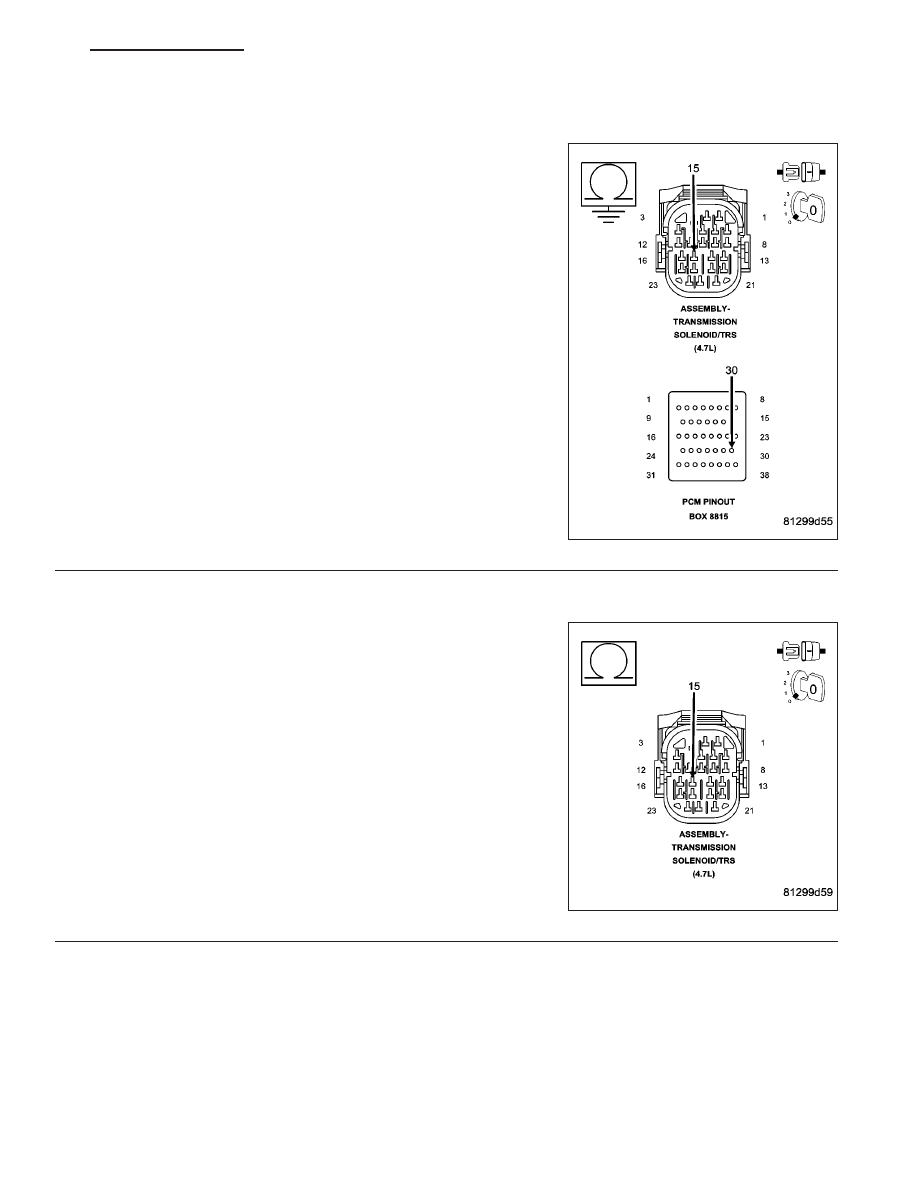
(T147) 2C PRESSURE SWITCH SENSE CIRCUIT SHORT TO GROUND

Measure the resistance between ground and the (T147) 2C Pressure
Switch Sense circuit.

Is the resistance below 5.0 ohms?

Yes

>> Repair the (T147) 2C Pressure Switch Sense circuit for a

short to ground.

Perform 45RFE/545RFE TRANSMISSION VERIFICATION
TEST - VER 1.

No

>> Go To 14

14.

(T147) 2C PRESSURE SWITCH SENSE CIRCUIT SHORT TO ANOTHER CIRCUIT

Measure the resistance between the (T147) 2C Pressure Switch
Sense circuit and all the other circuits in the Transmission Solenoid/
TRS Assembly harness connector.

Is the resistance below 5.0 ohms?

Yes

>> Repair the (T147) 2C Pressure Switch Sense circuit for a

short to another circuit(s).

Perform 45RFE/545RFE TRANSMISSION VERIFICATION
TEST - VER 1.

No

>> Replace the Powertrain Control Module per the Service

Information. With the scan tool, perform the QUICK
LEARN procedure.

Perform 45RFE/545RFE TRANSMISSION VERIFICATION
TEST - VER 1.

HB

AUTOMATIC TRANSMISSION 545RFE - ELECTRICAL DIAGNOSTICS

21 - 469

P0846-2C PRESSURE SWITCH RATIONALITY (CONTINUED)

15.

#5 AND/OR #7 CHECK BALL CUT OR DAMAGED

Turn the Ignition off to the lock position.

Remove the Valve Body Assembly per the Service Information.

Inspect the #5 and #7 check balls for any cuts or damage.

Inspect the 2C accumulator piston and seals and also the 2C tower seal on top of the valve body. Refer to the
Service Information.

Where there any problems found?

Yes

>> Repair as necessary. Check for excessive clutch debris in the transmission oil pan. If excessive clutch

debris is present, repair 2C clutch as necessary. Refer to the Service Information for proper repair pro-
cedures.

Perform 45RFE/545RFE TRANSMISSION VERIFICATION TEST - VER 1.

No

>> Go To 16

16.

EXCESSIVE FLUID LEAKAGE WITH 2C CLUTCH CIRCUIT

Air check the 2C Clutch hydraulic circuit. Refer to the Service Information.

NOTE: This hydraulic clutch circuit contains a small bleed orifice. Small leakage is considered normal.

Was there excessive air leakage in the 2C Clutch hydraulic circuit?

Yes

>> Repair as necessary. Refer to the Service Information.

Perform 45RFE/545RFE TRANSMISSION VERIFICATION TEST - VER 1.

No

>> Replace the Transmission Solenoid/TRS Assembly per the Service Information.

Perform 45RFE/545RFE TRANSMISSION VERIFICATION TEST - VER 1.

21 - 470

AUTOMATIC TRANSMISSION 545RFE - ELECTRICAL DIAGNOSTICS

HB

P0868-LINE PRESSURE LOW

HB

AUTOMATIC TRANSMISSION 545RFE - ELECTRICAL DIAGNOSTICS

21 - 471

P0868-LINE PRESSURE LOW (CONTINUED)

For the Transmission circuit diagram (Refer to 21 - TRANSMISSION/TRANSAXLE/AUTOMATIC - 45RFE/545RFE -
SCHEMATICS AND DIAGRAMS).

For a complete wiring diagram Refer to Section 8W

When Monitored:
Continuously while driving in a forward gear.

Set Condition:
The PCM continuously monitors Actual Line Pressure and compares it to Desired Line Pressure. If the Actual
Line Pressure is more than 10 PSI below Desired Line Pressure, this DTC will set.

Possible Causes

CHECK FOR RELATED DTC’S

LOW FLUID LEVEL

(F856) 5-VOLT SUPPLY CIRCUIT OPEN

POOR LINE PRESSURE SENSOR CONNECTION

(F856) 5-VOLT SUPPLY CIRCUIT SHORT TO GROUND

(F856) 5-VOLT SUPPLY CIRCUIT SHORT TO VOLTAGE

(T140) PRESSURE CONTROL SOLENOID CONTROL CIRCUIT SHORT TO ANOTHER CIRCUIT

INTERNAL TRANSMISSION

LINE PRESSURE SENSOR

CRACKED, PLUGGED, OR MISINSTALLED PRIMARY OIL FILTER

STUCK OR STICKING MAIN REGULATOR VALVE

POWERTRAIN CONTROL MODULE

Always perform the Pre-Diagnostic Troubleshooting procedure before proceeding. (Refer to 21 - TRANSMIS-
SION/TRANSAXLE/AUTOMATIC - 45RFE/545RFE - DIAGNOSIS AND TESTING).

Theory of Operation

Line pressure is measured by the Line Pressure Sensor (LPS) and regulation is achieved by changing the duty
cycle of the Pressure Control Solenoid (PCS) controlled by the Transmission Control System. (5% duty cycle =
solenoid off = max line pressure, 62% duty cycle = solenoid on = min line pressure). The Transmission Control
System calculates the desired line pressure based on inputs from both the engine and transmission.

The Transmission Control System calculates torque input to the transmission and uses it as the primary input to the
desired line pressure calculation. This is called Torque Based Line Pressure. In addition, the line pressure is set to
a preset level 827 or 931 kPa (120 or 135 PSI) during shifts and in Park and Neutral to ensure consistent shift
quality. The desired line pressure is continuously being compared to the actual line pressure. If the actual line pres-
sure is consistently lower than the target while driving, the line pressure low DTC P0868 will set.

Diagnostic Test

1.

CHECK FOR RELATED DTC’S

With the scan tool, check for other transmission DTC’s

Is the DTC P0932 present also?

Yes

>> Refer to the Transmission category and perform the appropriate symptom.

Perform 45RFE/545RFE TRANSMISSION VERIFICATION TEST - VER 1.

No

>> Go To 2

21 - 472

AUTOMATIC TRANSMISSION 545RFE - ELECTRICAL DIAGNOSTICS

HB


Content   ..  1264  1265  1266  1267   ..