Dodge Durango (HB). Manual - part 123


  Index      Dodge     Dodge Durango (HB) - service repair manual 2005 year


Search            


Content   ..  121  122  123  124   ..


Dodge Durango (HB). Manual - part 123


SCHEMATICS AND DIAGRAMS
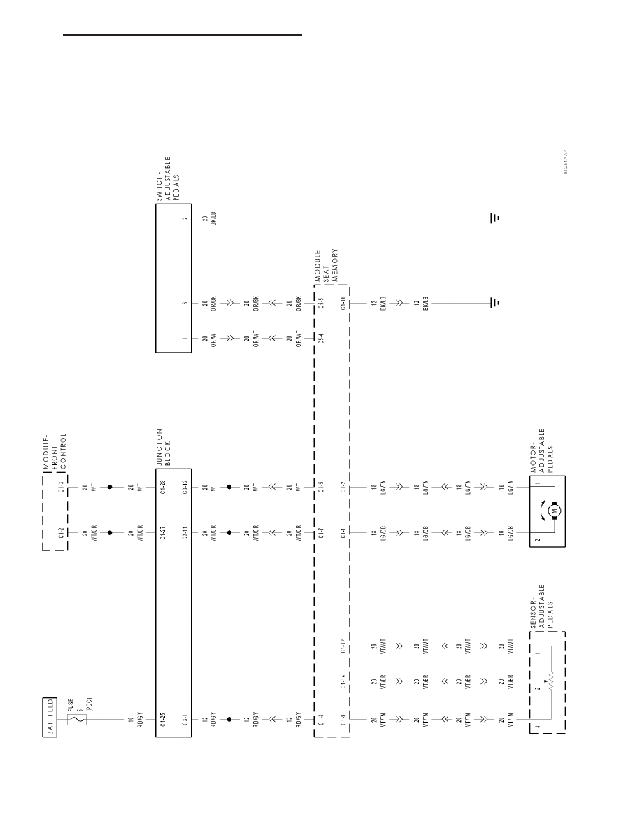
ADJUST

ABLE

PEDALS

SYSTEM

HB

BRAKES - ABS ELECTRICAL DIAGNOSTICS

5 - 271

BRAKES - ABS SERVICE INFORMATION

TABLE OF CONTENTS

page

page

BRAKES - ABS SERVICE INFORMATION

DESCRIPTION

. . . . . . . . . . . . . . . . . . . . . . . . 272

OPERATION

. . . . . . . . . . . . . . . . . . . . . . . . . . 272

DIAGNOSIS AND TESTING

ANTILOCK BRAKE SYSTEM

. . . . . . . . . . . . 273

STANDARD PROCEDURE

ABS BRAKE BLEEDING

. . . . . . . . . . . . . . . . 274

SPECIFICATIONS

TORQUE CHART

. . . . . . . . . . . . . . . . . . . . . 274

ELECTRICAL

DESCRIPTION

WHEEL SPEED SENSORS

. . . . . . . . . . . . . 274

SENSOR-WHEEL SPEED-ABS-FRONT

OPERATION

. . . . . . . . . . . . . . . . . . . . . . . . . . 275

REMOVAL

. . . . . . . . . . . . . . . . . . . . . . . . . . . . 276

INSTALLATION

. . . . . . . . . . . . . . . . . . . . . . . . 276

SENSOR-WHEEL SPEED-ABS-REAR

REMOVAL

WITH TRACTION CONTROL

. . . . . . . . . . . . 277

WITHOUT TRACTION CONTROL

. . . . . . . . . 277

INSTALLATION

WITH TRACTION CONTROL

. . . . . . . . . . . . 278

WITHOUT TRACTION CONTROL

. . . . . . . . . 278

SENSOR-G

DESCRIPTION

4X4 WITHOUT TRACTION CONTROL

. . . . . 278

4X4 WITH TRACTION CONTROL

. . . . . . . . . 279

OPERATION

4X4 WITH TRACTION CONTROL

. . . . . . . . . 279

REMOVAL – 4X4 WITH TRACTION CONTROL

. 279

INSTALLATION – 4X4 WITH TRACTION

CONTROL

. . . . . . . . . . . . . . . . . . . . . . . . . . 280

HYDRAULIC/MECHANICAL

DESCRIPTION - ELECTRONIC VARIABLE

BRAKE PROPORTIONING

. . . . . . . . . . . . . . 280

OPERATION - ELECTRONIC VARIABLE

BRAKE PROPORTIONING

. . . . . . . . . . . . . . 280

HCU (HYDRAULIC CONTROL UNIT)

DESCRIPTION

. . . . . . . . . . . . . . . . . . . . . . . . 280

OPERATION

. . . . . . . . . . . . . . . . . . . . . . . . . . 280

REMOVAL

. . . . . . . . . . . . . . . . . . . . . . . . . . . . 281

INSTALLATION

. . . . . . . . . . . . . . . . . . . . . . . . 283

BRAKES - ABS SERVICE INFORMATION

DESCRIPTION

The antilock brake system (ABS) is an electronically operated, three channel brake control system. The vehicle has
Electronic Brakeforce Distribution (EBD) designed into the system which eliminates the combination/proportioning
valve.

The system is designed to prevent wheel lockup and maintain steering control during braking. Preventing lockup is
accomplished by modulating fluid pressure to the wheel brake units.

The hydraulic system is a four channel design with traction control. The front wheel brakes are controlled individu-
ally and the rear wheel brakes in individually. The ABS electrical system is separate from other electrical circuits in
the vehicle. A specially programmed controller antilock brake unit operates the system components.

ABS system major components include:

Antilock Brake Module (ABM)

Hydraulic Control Unit (HCU)

Wheel Speed Sensors (WSS)

G-Sensor

ABS Warning Light

OPERATION

When wheel slip is detected during a brake application, the ABS enters antilock mode. During antilock braking,
hydraulic pressure in the individual wheel circuits is controlled to prevent any wheel from slipping. A separate
hydraulic line and specific solenoid valves are provided for each wheel. The ABS can decrease, hold, or increase
hydraulic pressure to each wheel brake. The ABS cannot, however, increase hydraulic pressure above the amount
which is transmitted by the master cylinder during braking

5 - 272

BRAKES - ABS SERVICE INFORMATION

HB

During antilock braking, a series of rapid pulsations is felt in the brake pedal. These pulsations are caused by the
rapid changes in position of the individual solenoid valves as the ICU responds to wheel speed sensor inputs and
attempts to prevent wheel slip. These pedal pulsations are present only during antilock braking and stop when nor-
mal braking is resumed or when the vehicle comes to a stop. A ticking or popping noise may also be heard as the
solenoid valves cycle rapidly. During antilock braking on dry pavement, intermittent chirping noises may be heard as
the tires approach slipping. These noises and pedal pulsations are considered normal during antilock operation.

Vehicles equipped with ABS may be stopped by applying normal force to the brake pedal. Brake pedal operation
during normal braking is no different than that of previous non-ABS systems. Maintaining a constant force on the
brake pedal provides the shortest stopping distance while maintaining vehicle stability.

PRESSURE DECREASE

The ICU (Integrated Control Unit) decreases the pressure to individual wheels during a deceleration when wheel slip
occurs. The inlet valve is closed and the outlet valve is opened. The excess fluid is stored in the accumulator until
the return pump can return the fluid to the master cylinder.

PRESSURE HOLD

The ICU closes the inlet valve and keeps the outlet valve closed in order to isolate the system when wheel slip
occurs. This holds the pressure steady on the brake so that the hydraulic pressure does not increase or decrease.

PRESSURE INCREASE

The ICU increases the pressure to individual wheels during a deceleration in order to reduce the speed of the
wheel. The inlet valve is opened and the outlet valve is closed. The increased pressure is delivered from the master
cylinder.

ELECTRONIC BRAKEFORCE DISTRIBUTION (EBD)

The electronic brakeforce distribution (EBD) is a control system that replaces the hydraulic proportioning function of
the mechanical proportioning valve in the base brake system. The EBD control system is part of the operation soft-
ware in the ICU. The EBD uses active control with existing ABS in order to regulate the vehicle’s rear brake pres-
sure. The red brake warning indicator is illuminated when the dynamic rear proportioning function is disabled.

TRACTION CONTROL (TCS)

The primary function of the Traction Control System (TCS) is to optimize vehicle performance with varying vehicle
load and changing road conditions by controlling wheel slip at the driven wheels during an acceleration maneuver.
The wheel slip is controlled by actively applying braking force. This modulation is applied and occur under all throttle
input conditions where the difference between wheel speed’ and vehicle speed indicate a loss of longitudinal trac-
tion. TCS operation for each mode of driveline operation include the following. When high range is selected for the
transfer case, the system controls wheel slip in the order of stability and acceleration. When low range is selected
for the transfer case, the system controls wheel slip in the order of acceleration and stability. The TCS switch turns
the system on/off. The braking is accomplished by closing the TCS Master Cylinder Isolating Valve, this isolates the
master cylinder from the rest of the system. The TCS Prime valve opens to allow the pump to get brake fluid to
build pressure for braking. The drive wheel circuit solenoids are energized as needed to allow for pressure hold,
pressure increase, or pressure decrease

DIAGNOSIS AND TESTING

ANTILOCK BRAKE SYSTEM

Diagnosis of base brake conditions which are mechanical in nature should be performed first. This includes brake
noise, lack of power assist, parking brake, or vehicle vibration during normal braking.

The Anitilock brake system performs several self-tests every time the ignition switch is turned on and the vehicle is
driven. The ABM monitors the system inputs and outputs circuits to verify the system is operating properly. If the
ABM senses a malfunction in the system it will set a DTC into memory and trigger the warning lamp.

HB

BRAKES - ABS SERVICE INFORMATION

5 - 273

NOTE: The scan tool is used to diagnose the Anitlock Braking System. For test procedures refer to the
Chassis Diagnostic Manual.

STANDARD PROCEDURE

ABS BRAKE BLEEDING

ABS system bleeding requires conventional bleeding methods plus use of the scan tool. The procedure involves
performing a base brake bleeding, followed by use of the scan tool to cycle and bleed the HCU pump and sole-
noids. A second base brake bleeding procedure is then required to remove any air remaining in the system.

1. Perform base brake bleeding, (Refer to 5 - BRAKES - STANDARD PROCEDURE) OR (Refer to 5 - BRAKES -

STANDARD PROCEDURE).

2. Connect scan tool to the Data Link Connector.

3. Select ANTILOCK BRAKES, followed by MISCELLANEOUS, then ABS BRAKES. Follow the instructions dis-

played. When scan tool displays TEST COMPLETE, disconnect scan tool and proceed.

4. Perform base brake bleeding a second time, (Refer to 5 - BRAKES - STANDARD PROCEDURE) OR (Refer to

5 - BRAKES - STANDARD PROCEDURE).

5. Top off master cylinder fluid level and verify proper brake operation before moving vehicle.

SPECIFICATIONS

TORQUE CHART

TORQUE SPECIFICATIONS

DESCRIPTION

N·m

Ft. Lbs.

In. Lbs.

HCU Assembly

Mounting Bolts

15

11

ABM Mounting Screws

6

53

ABS Assembly

Brake Line Fittings

19

170

Wheel Speed Sensors

Front Sensor Bolt

21

190

Rear Wheel Speed Sensor

Mounting Bolt

24

200

G-Sensor

With (TCS)

5.6

50

ELECTRICAL

DESCRIPTION

WHEEL SPEED SENSORS

The ABS brake system uses 3 or 4 wheel speed sensors. Vehicles with traction control use 4 sensors, individual
sensors are mounted to each front and rear hub/bearings. Vehicles without traction control use 3 sensors, 2 indi-
vidual sensors are mounted to the front hub/bearing and the third sensor is mounted on top of the rear axle differ-
ential housing. 4X4 vehicles without traction control use a G-sensor that is internally located in the ABM and is
not serviced separately. 4X4 vehicles with traction control use a G-sensor that is located under the Instrument
Top Cover and can be serviced separately.

5 - 274

BRAKES - ABS SERVICE INFORMATION

HB


Content   ..  121  122  123  124   ..