Dodge Durango (HB). Manual - part 121


  Index      Dodge     Dodge Durango (HB) - service repair manual 2005 year


Search            


Content   ..  119  120  121  122   ..


Dodge Durango (HB). Manual - part 121


C2200-ANTI—LOCK BRAKE MODULE INTERNAL (CONTINUED)

For the ABS circuit diagram (Refer to 5 - BRAKES - SCHEMATICS AND DIAGRAMS)

For a complete wiring diagram Refer to Section 8W.

When Monitored:
Ignition on. The Anti—lock brake module monitors its internal microprocessors for correct operation.

Set Condition:
If the Anti—lock brake module detects an internal fault, the DTC is set.

Possible Causes

ABM - GROUND CIRCUIT OPEN

ABS FUSED B(+) CIRCUIT OPEN

ABS PUMP FUSED B(+) CIRCUIT OPEN

ABM - INTERNAL FAULT

Diagnostic Test

1.

ABM INTERNAL FAILURE DTC PRESENT

Turn the ignition on.

With the scan tool, read DTCs.

With the scan tool, erase DTCs.

Turn the ignition off.

Turn the ignition on.

With the scan tool, read DTCs.

Does the scan tool display ANTI—LOCK BRAKE MODULE
INTERNAL FAILURE?

Yes

>> Go To 2

No

>> Refer to the INTERMITTENT CONDITION Diagnostic

Procedure.

2.

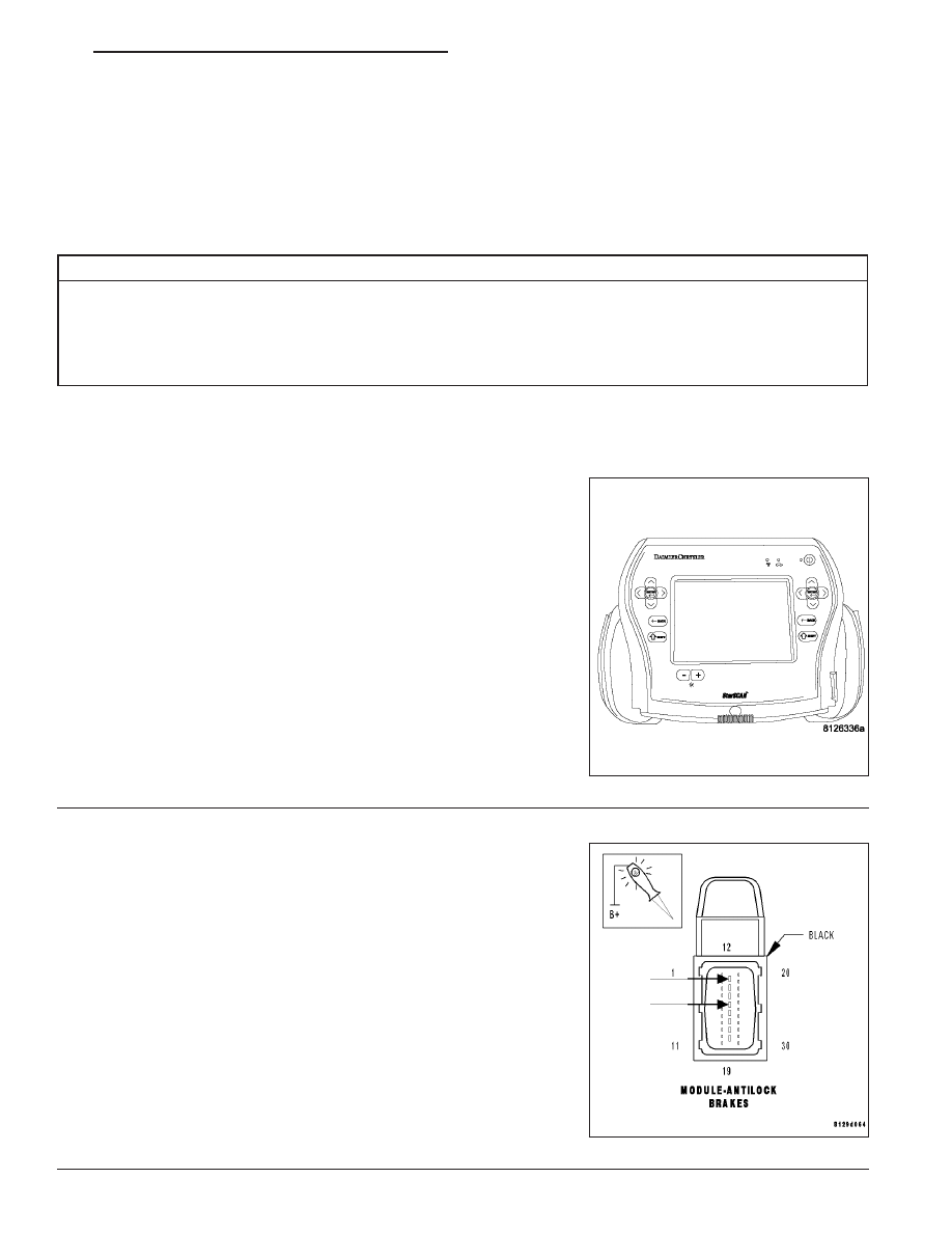
CAB - GROUND CIRCUIT OPEN

Turn the ignition off.

Disconnect the ABM harness connector.

Note: Check clean connectors and terminals,.

Using a 12-volt test light connected to 12-volts, probe the ABM har-
ness connector ground circuits.

Did the test light illuminate?

Yes

>> Go To 3

No

>> Repair the ABM Ground circuit for an open.

Perform ABS VERIFICATION TEST - VER 1.

HB

BRAKES - ABS ELECTRICAL DIAGNOSTICS

5 - 263

C2200-ANTI—LOCK BRAKE MODULE INTERNAL (CONTINUED)

3.

ABS FUSED B(+) CIRCUIT OPEN

Turn the ignition on.

Using a 12-volt test light connected to ground, probe the ABS Fused
B(+) circuit at the ABM harness connector.

Did the test light illuminate?

Yes

>> Go To 4

No

>> Repair the ABS Valve Fused B(+) circuit for an open.

Perform ABS VERIFICATION TEST - VER 1.

4.

ABS PUMP FUSED B(+) CIRCUIT OPEN

Using a 12-volt test light connected to ground, probe the ABS Pump
Fused B(+) circuit at the ABM harness connector.

Did the test light illuminate?

Yes

>> Replace the Anti—lock brake module in accordance with

the Service Information.

Perform ABS VERIFICATION TEST - VER 1.

No

>> Repair the ABS Pump Fused B(+) circuit for an open.

Perform ABS VERIFICATION TEST - VER 1.

5 - 264

BRAKES - ABS ELECTRICAL DIAGNOSTICS

HB

C2202-VIN 1 MISMATCH/MISSING

HB

BRAKES - ABS ELECTRICAL DIAGNOSTICS

5 - 265

C2202-VIN 1 MISMATCH/MISSING (CONTINUED)

For the ABS circuit diagram (Refer to 5 — BRAKES — SCHEMATICS AND DIAGRAMS).

For a complete wiring diagram Refer to Section 8W.

When Monitored:
At power up, VIN is read off the CAN bus, If the VIN message is not received then the VIN stored in EEPROM
is used for the comparison.

Set Condition:
The VIN stored in the ABM does not match the VIN read off of the CAN bus. The 5th character in the VIN
should be ’D’ for 4x2 or ’B’ for4x4.

Possible Causes

WRONG MODULE

WRONG VIN PROGRAMED INTO VEHICLE

Diagnostic Test

1.

WRONG VIN PROGRMED INTO VEHICLE

NOTE: 4x4 vehicles have different modules than 4x2 vehicles

Is the correct VIN programed into the vehicle?

Yes

>> Replace the Anti-lock brake module with the correct module.

Perform ABS VERIFICATION TEST — VER 1.

No

>> Reprogram the VIN per service information.

Perform ABS VERIFICATION TEST — VER 1.

5 - 266

BRAKES - ABS ELECTRICAL DIAGNOSTICS

HB


Content   ..  119  120  121  122   ..