Dodge Durango (HB). Manual - part 1217


  Index      Dodge     Dodge Durango (HB) - service repair manual 2005 year


Search            


Content   ..  1215  1216  1217  1218   ..


Dodge Durango (HB). Manual - part 1217


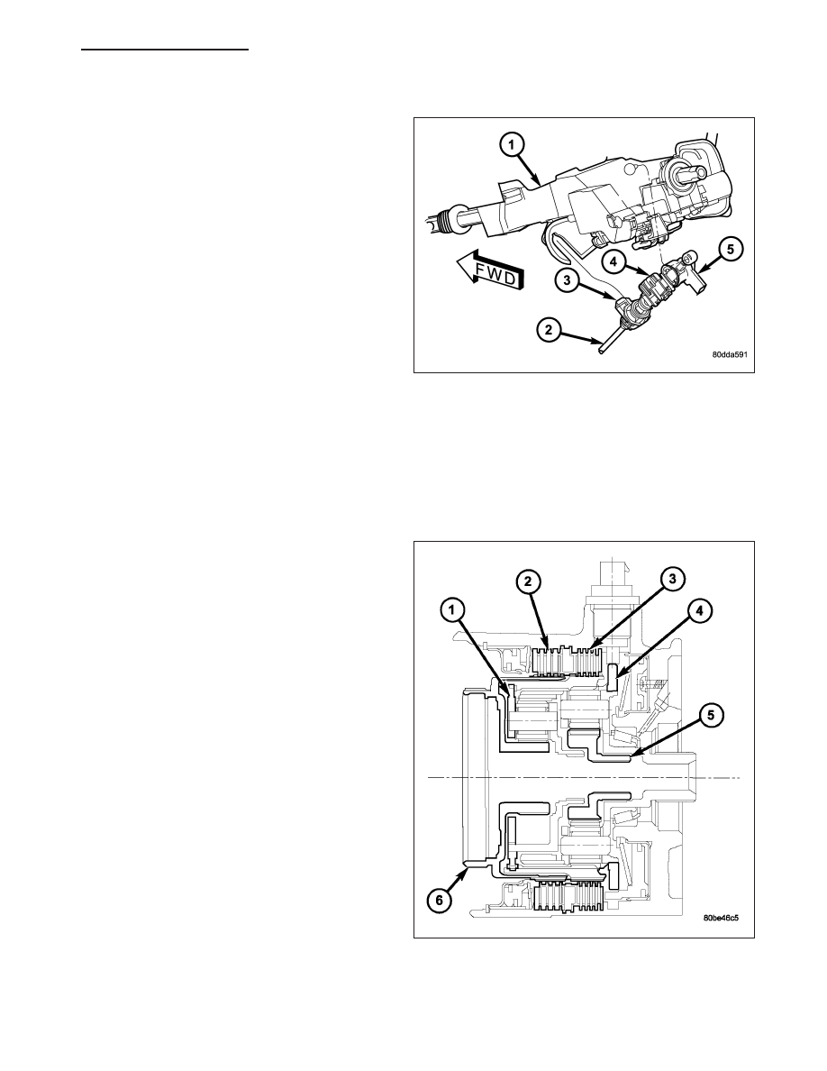
Gearshift Adjustment Procedure

1. Shift transmission into PARK.

2. Release cable adjuster lock tab (3) (underneath the

steering column) to unlock cable.

3. Raise vehicle.

4. Disengage the cable eyelet from the transmission

manual shift lever.

5. Verify transmission shift lever is in PARK detent by

moving lever fully rearward. Last rearward detent is
PARK position.

6. Verify positive engagement of transmission park

lock by attempting to rotate propeller shaft. Shaft
will not rotate when park lock is engaged.

7. Snap the cable eyelet onto the transmission man-

ual shift lever.

8. Lower vehicle.

9. Lock shift cable by pressing cable adjuster lock tab (3) downward until it snaps into place.

10. Check engine starting. Engine should start only in PARK and NEUTRAL.

CLUTCHES-HOLDING

DESCRIPTION

Two hydraulically applied multi-disc clutches are used
to hold planetary geartrain components stationary
while the input clutches drive others. The 2/4 (2) and
Low/Reverse (3) clutches are considered holding
clutches and are contained at the rear of the transmis-
sion case.

OPERATION

NOTE: (Refer to 21 - TRANSMISSION/AUTOMATIC - 42RLE - DIAGNOSIS AND TESTING) for a collective view
of which clutch elements are applied at each position of the selector lever.

HB

AUTOMATIC TRANSMISSION 42RLE - SERVICE INFORMATION

21 - 273

2/4 CLUTCH

The 2/4 clutch is hydraulically applied in second and fourth gears by pressurized fluid against the 2/4 clutch piston.
When the 2/4 clutch is applied, the front sun gear assembly is held or grounded to the transmission case.

LOW/REVERSE CLUTCH

The Low/Reverse clutch is hydraulically applied in park, reverse, neutral, and first gears by pressurized fluid against
the Low/Reverse clutch piston. When the Low/Reverse clutch is applied, the front planet carrier/rear annulus assem-
bly is held or grounded to the transmission case.

ASSEMBLY-INPUT CLUTCH

DISASSEMBLY

1. Mount input clutch assembly to Input Clutch Pres-

sure Fixture (Tool 8391).

2. Tap down (2) reverse clutch reaction plate (4) to

release pressure from snap ring.

3. Remove reverse clutch snap ring (3).

21 - 274

AUTOMATIC TRANSMISSION 42RLE - SERVICE INFORMATION

HB

4. Pry up reverse clutch reaction plate (1).

5. Remove reverse clutch reaction plate (1).

NOTE: Tag reverse clutch pack for reassembly
identification.

6. Remove the reverse clutch pack (two fibers/one

steel) (1, 2).

HB

AUTOMATIC TRANSMISSION 42RLE - SERVICE INFORMATION

21 - 275

7. Remove the OD/Reverse reaction plate (1) snap

ring (3).

8. Remove OD/Reverse pressure plate (1).

9. Remove OD/Reverse reaction plate wave snap ring

(2).

21 - 276

AUTOMATIC TRANSMISSION 42RLE - SERVICE INFORMATION

HB


Content   ..  1215  1216  1217  1218   ..