Dodge Durango (HB). Manual - part 1136


  Index      Dodge     Dodge Durango (HB) - service repair manual 2005 year


Search            


Content   ..  1134  1135  1136  1137   ..


Dodge Durango (HB). Manual - part 1136


4.7L V-8

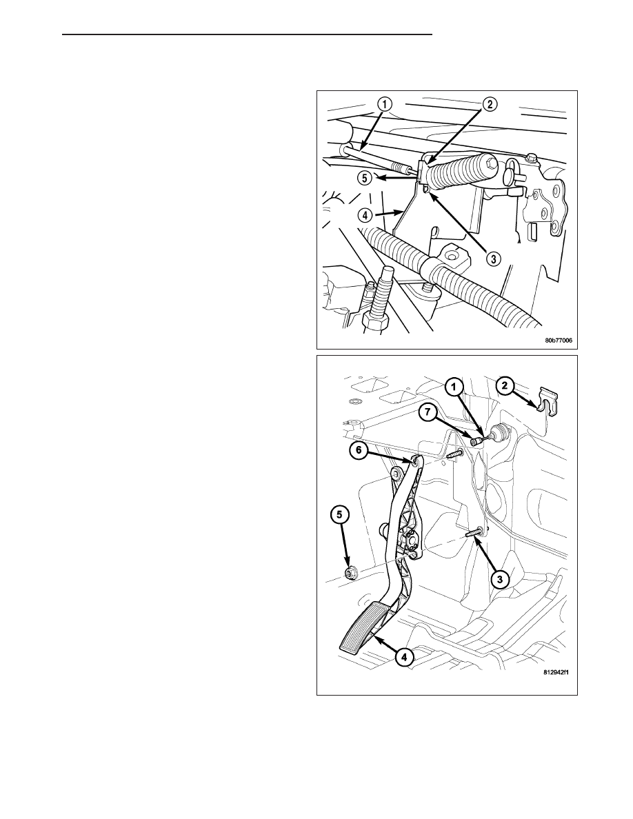
1. Slide accelerator cable plastic mount into bracket.

Continue sliding until tab (3) is aligned to hole in
mounting bracket.

2. Route accelerator cable over top of cable cam.

3. Connect cable end to throttle body bellcrank pin

(snaps on rearward).

4. Slide rubber grommet away from plastic cable

housing.

5. Install rubber grommet into dash panel until seated.

6. Push cable housing into rubber grommet and

through opening in dash panel.

7. From inside vehicle, install clip (2) holding cable to

dashpanel.

8. From inside vehicle, slide throttle cable core wire

into opening (6) in top of pedal arm.

9. Push cable retainer (clip) (7) into pedal arm open-

ing (6) until it snaps in place.

10. Snap cable into dashpanel routing clip.

11. Install air resonator tube to throttle body.

12. Before starting engine, operate accelerator pedal

to check for any binding.

HB

FUEL INJECTION

14 - 55

SENSOR-THROTTLE POSITION

DESCRIPTION

The 3-wire Throttle Position Sensor (TPS) is mounted on the throttle body and is connected to the throttle blade
shaft.

The 5.7L V-8 engine does not use a separate TPS on the throttle body.

OPERATION

The 5.7L V-8 engine does not use a separate Throttle Position Sensor (TPS) on the throttle body.

The 3–wire TPS provides the Powertrain Control Module (PCM) with an input signal (voltage) that represents the
throttle blade position of the throttle body. The sensor is connected to the throttle blade shaft. As the position of the
throttle blade changes, the output voltage of the TPS changes.

The PCM supplies approximately 5 volts to the TPS. The TPS output voltage (input signal to the PCM) represents
the throttle blade position. The PCM receives an input signal voltage from the TPS. This will vary in an approximate
range of from .26 volts at minimum throttle opening (idle), to 4.49 volts at wide open throttle. Along with inputs from
other sensors, the PCM uses the TPS input to determine current engine operating conditions. In response to engine
operating conditions, the PCM will adjust fuel injector pulse width and ignition timing.

The PCM needs to identify the actions and position of the throttle blade at all times. This information is needed to
assist in performing the following calculations:

Ignition timing advance

Fuel injection pulse-width

Idle (learned value or minimum TPS)

Off-idle (0.06 volt)

Wide Open Throttle (WOT) open loop (2.608 volts above learned idle voltage)

Deceleration fuel lean out

Fuel cutoff during cranking at WOT (2.608 volts above learned idle voltage)

A/C WOT cutoff (certain automatic transmissions only)

REMOVAL

3.7L V6

The Throttle Position Sensor (TPS) is mounted to the
throttle body (1).

1. Remove air resonator tube at throttle body.

2. Disconnect TPS electrical connector.

3. Remove two TPS mounting screws (2).

4. Remove TPS.

14 - 56

FUEL INJECTION

HB

4.7L V-8

The TPS is located on the throttle body (2).

1. Remove air duct and tube at throttle body.

2. Disconnect TPS electrical connector.

3. Remove two TPS mounting bolts (screws) (5).

4. Remove TPS from throttle body.

5.7L V-8

The 5.7L V-8 engine does not use a separate Throttle Position Sensor (TPS) on the throttle body.

HB

FUEL INJECTION

14 - 57

INSTALLATION

3.7L V-6

The throttle shaft end of throttle body (3) slides into a
socket in TPS (4). The TPS must be installed so that
it can be rotated a few degrees. (If sensor will not
rotate, install sensor with throttle shaft on other side of
socket tangs). The TPS will be under slight tension
when rotated.

1. Install TPS and retaining screws.

2. Tighten screws to 7 N·m (60 in. lbs.) torque.

3. Connect TPS electrical connector to TPS.

4. Manually operate throttle (by hand) to check for

any TPS binding before starting engine.

5. Install air cleaner tube to throttle body.

4.7L V-8

The throttle shaft end of throttle body (5) slides into a
socket in TPS (4). The TPS must be installed so that
it can be rotated a few degrees. If sensor will not
rotate, install sensor with throttle shaft on other side of
socket tangs. The TPS will be under slight tension
when rotated.

1. Install TPS and two retaining bolts.

2. Tighten bolts to 7 N·m (60 in. lbs.) torque.

3. Manually operate throttle control lever by hand to

check for any binding of TPS.

4. Connect TPS electrical connector to TPS.

5. Install air duct/air box to throttle body.

14 - 58

FUEL INJECTION

HB


Content   ..  1134  1135  1136  1137   ..