Content .. 1012 1013 1014 1015 ..
Dodge Durango (HB). Manual - part 1014
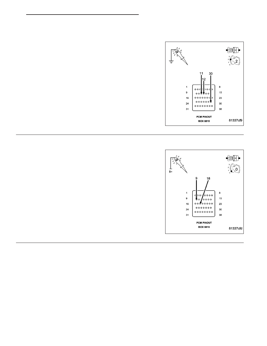
*NO RESPONSE WITH A NO START CONDITION (CONTINUED)
2.
(F1), (F202), AND (F924) PCM FUSED IGNITION SWITCH CIRCUITS
Using a 12-volt test light connected to ground, probe the PCM Fused
Ignition Switch Output circuit in the appropriate terminals of special
tool #8815.
Does the test light illuminate brightly?
Yes
>> Go To 3
No
>> Repair the (F1), (F202), and (F924) Ignition Switch Output
circuit. Inspect and replace fuses as necessary.
Perform the POWERTRAIN VERIFICATION TEST. (Refer
to 9 - ENGINE - STANDARD PROCEDURE)
3.
(Z913) (Z937) PCM GROUND CIRCUITS
Using a 12-volt test light connected to battery voltage, probe the
(Z913) (Z937) PCM ground circuits in the appropriate terminals of spe-
cial tool #8815.
Does the test light illuminate brightly?
Yes
>> Go To 4
No
>> Repair the (Z913) (Z937) PCM ground circuits.
Perform the POWERTRAIN VERIFICATION TEST. (Refer
to 9 - ENGINE - STANDARD PROCEDURE)
HB
ENGINE ELECTRICAL DIAGNOSTICS
9 - 1055