Content .. 998 999 1000 1001 ..
Dodge Durango (HB). Manual - part 1000
P2323-IGNITION COIL 8 SECONDARY CIRCUIT- INSUFFICIENT IONIZATION (CONTINUED)
3.
COIL ON PLUG RESISTANCE
Turn the ignition off.
NOTE: The following resistance measurement should be taken at 70°-80° F.
Measure the resistance of the Coil on Plug.
4.7L Primary Ignition Coil resistance is 0.6 to 0.9 of an ohm at 77°F (25°C).
5.7L Primary Ignition Coil resistance is 0.558 to 0.682 of an ohm at 77°F (25°C).
Is the resistance within the given specification for the Ignition Coil being tested?
Yes
>> Go To 4
No
>> Replace the Coil on plug.
Perform the POWERTRAIN VERIFICATION TEST. (Refer to 9 - ENGINE - STANDARD PROCEDURE)
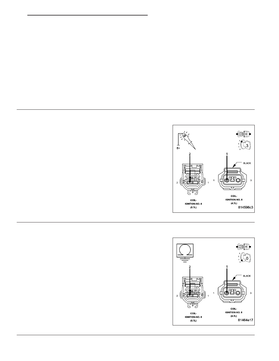
4.
IGNITION COIL
Using a 12-volt test light connected to a 12-volt source, probe the
(K98) Coil Control No.8 circuit.
Crank the engine for 5 seconds while observing the test light.
What is the state of the test light while cranking the engine?
Brightly blinking.
Replace the Coil on plug.
Perform the POWERTRAIN VERIFICATION TEST. (Refer
to 9 - ENGINE - STANDARD PROCEDURE)
ON constantly.
Go To 5
OFF constantly.
Go To 6
5.
(K98) COIL CONTROL NO.8 CIRCUIT SHORTED TO GROUND
Turn the ignition off.
Disconnect the C1 PCM harness connector.
Measure the resistance between ground and the (K98) Coil Control
No.8 circuit in the Coil on Plug harness connector.
Is the resistance below 100 ohms?
Yes
>> Repair the short to ground in the (K98) Coil Control No.8
circuit.
Perform the POWERTRAIN VERIFICATION TEST. (Refer
to 9 - ENGINE - STANDARD PROCEDURE)
No
>> Go To 7
HB
ENGINE ELECTRICAL DIAGNOSTICS
9 - 999