Index Dodge Dodge Durango (HB) - service repair manual 2005 year
Search
Content .. 89 90 91 92 ..
Dodge Durango (HB). Manual - part 91
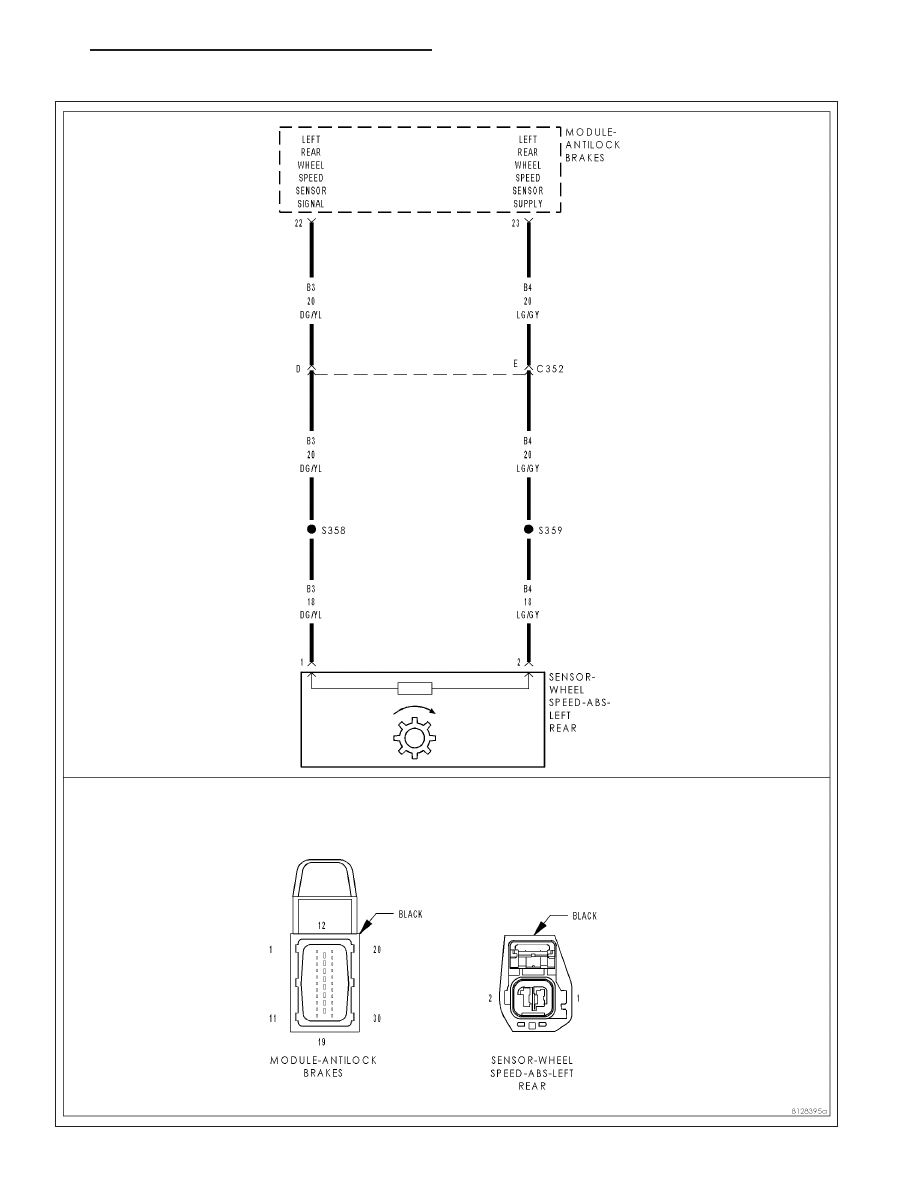
C1020–LEFT REAR WHEEL SPEED SENSOR CIRCUIT
HB
BRAKES - ABS ELECTRICAL DIAGNOSTICS
5 - 143