Index Dodge Dodge Durango (HB) - service repair manual 2005 year
Search
Content .. 85 86 87 88 ..
Dodge Durango (HB). Manual - part 87
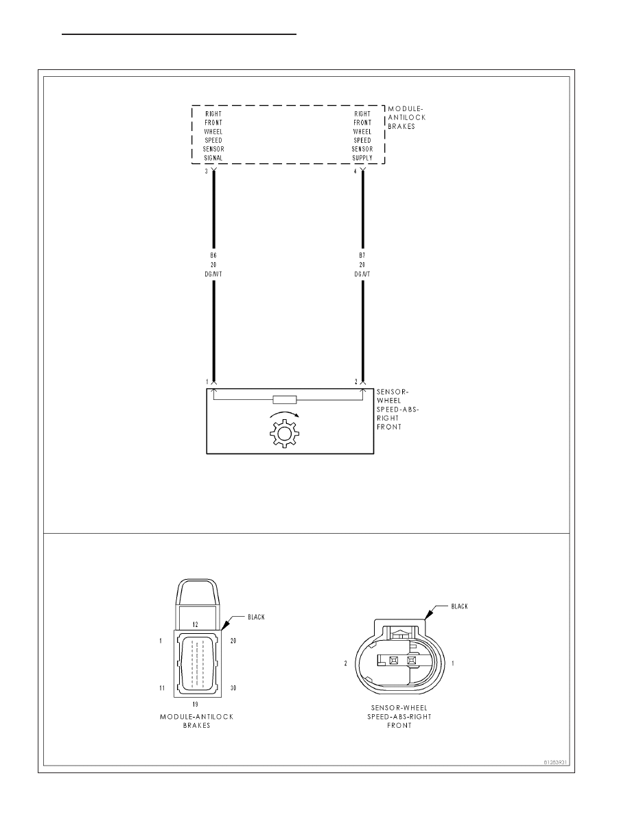
C1015–RIGHT FRONT WHEEL SPEED SENSOR CIRCUIT
HB
BRAKES - ABS ELECTRICAL DIAGNOSTICS
5 - 127