Index Dodge Dodge Durango (HB) - service repair manual 2005 year
Search
Content .. 81 82 83 84 ..
Dodge Durango (HB). Manual - part 83
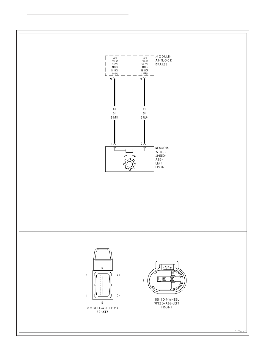
C100A–LEFT FRONT WHEEL SPEED SENSOR CIRCUIT
HB
BRAKES - ABS ELECTRICAL DIAGNOSTICS
5 - 111