Dodge Durango (HB). Manual - part 81


  Index      Dodge     Dodge Durango (HB) - service repair manual 2005 year


Search            


Content   ..  79  80  81  82   ..


Dodge Durango (HB). Manual - part 81


B1D67–ADJUSTABLE PEDAL CONTROL CIRCUIT PERFORMANCE (CONTINUED)

5.

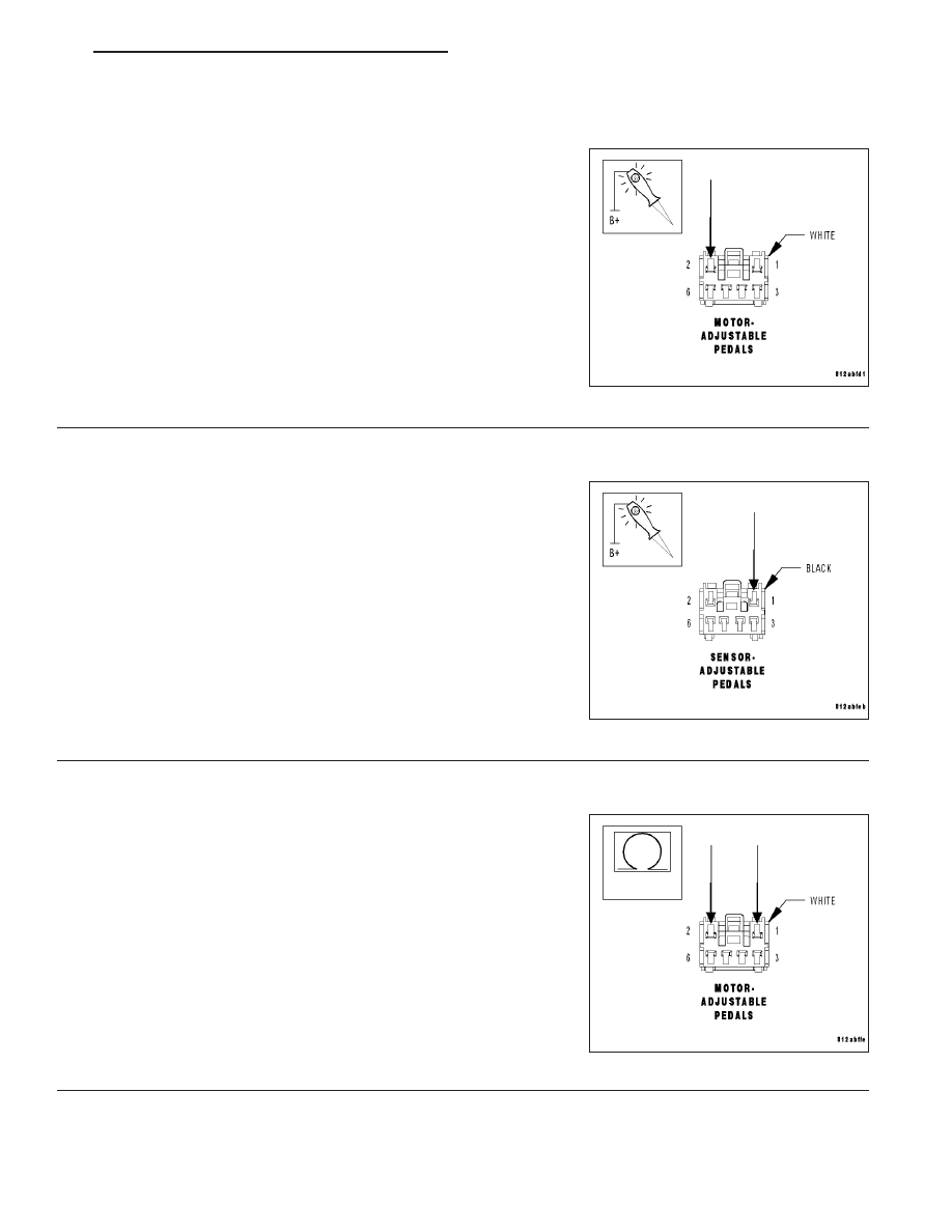
CHECK (P206) ADJUSTABLE PEDALS MOTOR REARWARD CIRCUIT FOR AN OPEN

Turn the ignition off.

Disconnect the Seat Memory Module harness connector.

Disconnect the Adjustable Pedals Motor harness connector

Connect a jumper wire between the (P206) Adjustable Pedals Motor
Rearward circuit and ground.

Using a 12-volt test light connected to 12-volts, probe the (P206)
Adjustable Pedals Motor Rearward circuit.

Does the test light illuminate brightly?

Yes

>> Go To 6

No

>> Repair the (P206) Adjustable Pedals Motor Rearward cir-

cuit for an open.

Perform APS VERIFICATION TEST - VER 1.

6.

CHECK (G912) ADJUSTABLE PEDALS SENSOR RETURN CIRCUIT FOR AN OPEN

Turn the ignition off.

Disconnect the Seat Memory Module harness connector.

Disconnect the Adjustable Pedals Sensor harness connector

Connect a jumper wire between the (G912) Adjustable Pedals Sensor
Return circuit and ground.

Using a 12-volt test light connected to 12-volts, probe the (G912)
Adjustable Pedals Sensor Return circuit.

Does the test light illuminate brightly?

Yes

>> Go To

No

>> Repair the (G912) Adjustable Pedals Sensor Return circuit

for an open.

Perform APS VERIFICATION TEST - VER 1.

7.

CHECK ADJUSTABLE PEDALS MOTOR

Turn the ignition off.

Disconnect the Adjustable Pedals Motor harness connector.

Measure the resistance between the (P205) Adjustable Pedals Motor
Forward and (P206) Adjustable Pedals Motor Rearward terminals at
the Adjustable Pedals Motor.

Is the resistance below 100.0 ohms?

Yes

>> Replace and reprogram the Seat Memory Module in

accordance with the Service Information.

Perform APS VERIFICATION TEST - VER 1.

No

>> Replace the Adjustable Pedals Motor in accordance with

the Service Information.

Perform APS VERIFICATION TEST - VER 1.

HB

BRAKES - ABS ELECTRICAL DIAGNOSTICS

5 - 103

C1008–BRAKE FLUID LEVEL INPUT CIRCUIT HIGH

5 - 104

BRAKES - ABS ELECTRICAL DIAGNOSTICS

HB

C1008–BRAKE FLUID LEVEL INPUT CIRCUIT HIGH (CONTINUED)

For the Anti-Lock Brake System circuit diagram. (Refer to 5 - BRAKES - SCHEMATICS AND DIAGRAMS)

For a complete wiring diagram Refer to Section 8W.

When Monitored:
With the ignition on.

Set Condition:
When above normal voltage is detected on the Brake Fluid Level Switch Sense circuit.

Possible Causes

BRAKE FLUID LEVEL SENSOR CONNECTOR DAMAGED

(B20) BRAKE FLUID LEVEL SWITCH SENSE CIRCUIT SHORTED TO VOLTAGE, OR OPEN

(Z420) GROUND CIRCUIT OPEN

BRAKE FLUID LEVEL SENSOR - INTERNAL FAULT

ANTI-LOCK BRAKE MODULE - INTERNAL FAULT

Diagnostic Test

1.

CHECK FOR DTC C1008–BRAKE FLUID LEVEL INPUT CIRCUIT HIGH

NOTE: This DTC must be active for the results of this test to be
valid.
Turn the ignition on.

With the scan tool, record and erase DTC’s.

Cycle the ignition switch from off to on.

With the scan tool, read DTC’s

Does the scan tool display: C1008–BRAKE FLUID LEVEL INPUT
CIRCUIT HIGH?

Yes

>> Go To 2

No

>> Refer to the INTERMITTENT CONDITION diagnostic pro-

cedure.

Perform ABS VERIFICATION TEST - VER 1.

HB

BRAKES - ABS ELECTRICAL DIAGNOSTICS

5 - 105

C1008–BRAKE FLUID LEVEL INPUT CIRCUIT HIGH (CONTINUED)

2.

CHECK BRAKE FLUID LEVEL SENSOR CONNECTION

Turn the ignition off.

Inspect the connection of the Brake Fluid Level Sensor harness con-
nector.

NOTE: Check all terminals for broken, bent, pushed out, or cor-
roded terminals.

Is there any damage?

Yes

>> Repair as necessary.

Perform ABS VERIFICATION TEST - VER 1.

No

>> Go To 3

3.

CHECK (B20) BRAKE FLUID LEVEL SWITCH SENSE CIRCUIT FOR A SHORT TO VOLTAGE

Turn the ignition off.

Disconnect the Anti-Lock Brake Module harness connector.

Disconnect the Brake Fluid Level Sensor harness connector.

Turn the ignition on.

Measure the voltage between (B20) Brake Fluid Level Switch Sense
circuit and ground.

Is there any voltage present?

Yes

>> Repair the (B20) Brake Fluid Level Switch Sense circuit

for a short to voltage.

Perform ABS VERIFICATION TEST - VER 1.

No

>> Go To 4

5 - 106

BRAKES - ABS ELECTRICAL DIAGNOSTICS

HB


Content   ..  79  80  81  82   ..