Index Dodge Dodge Durango (HB) - service repair manual 2005 year
Search
Content .. 74 75 76 77 ..
Dodge Durango (HB). Manual - part 76
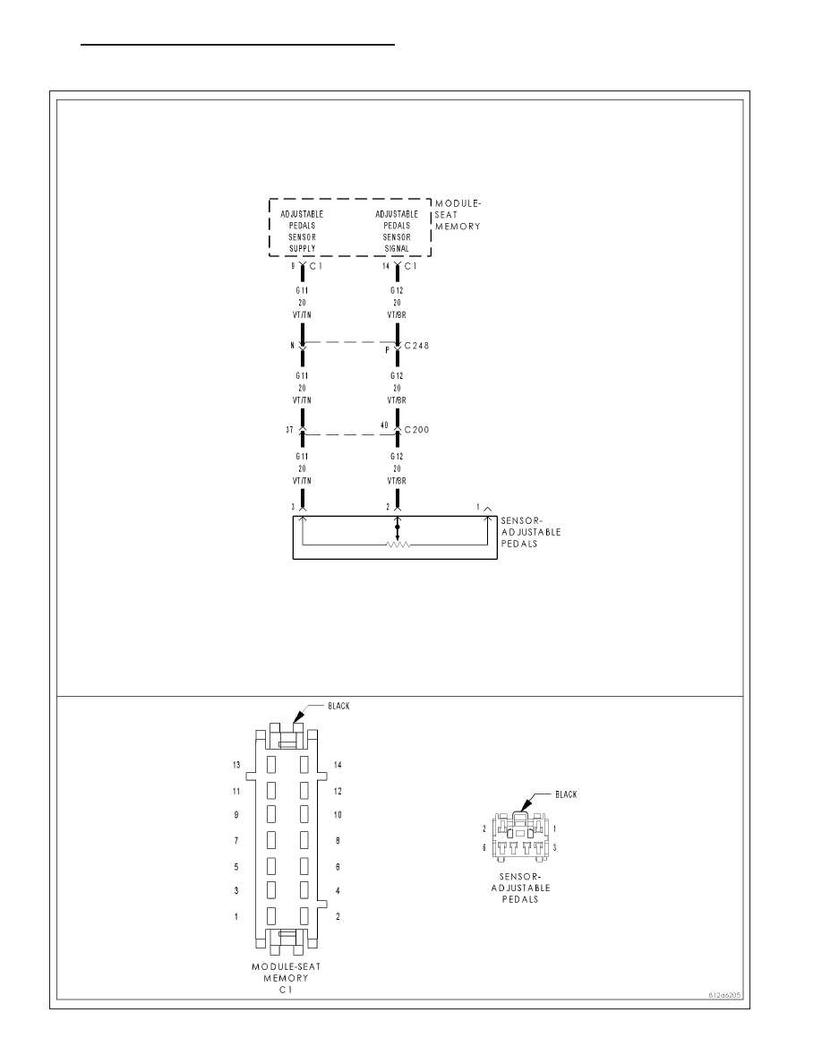
B1D57–ADJUSTABLE PEDAL SENSOR CIRCUIT HIGH
HB
BRAKES - ABS ELECTRICAL DIAGNOSTICS
5 - 83