Dodge Durango (HB). Manual - part 69


  Index      Dodge     Dodge Durango (HB) - service repair manual 2005 year


Search            


Content   ..  67  68  69  70   ..


Dodge Durango (HB). Manual - part 69


REAR

1. Raise and support the vehicle

2. Remove the tire and wheel assembly.

3. Remove the disc brake caliper (Refer to 5 -

BRAKES/HYDRAULIC/MECHANICAL/DISC
BRAKE CALIPERS - REMOVAL).

4. Remove the caliper adapter bolts. (Refer to 5 -

BRAKES/HYDRAULIC/MECHANICAL/DISC
BRAKE CALIPER ADAPTER - REMOVAL)

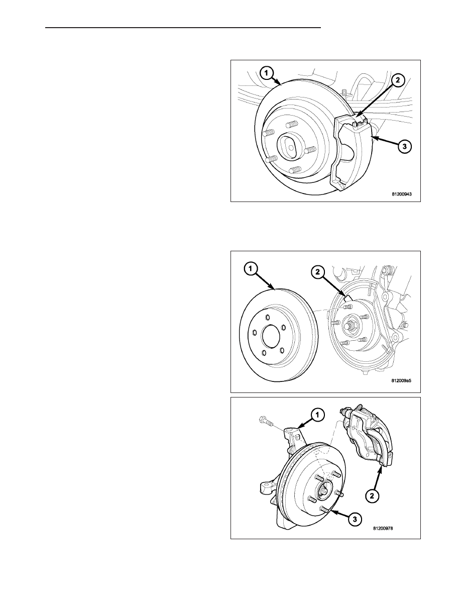
5. Remove the disc brake caliper adapter (2).

6. Remove the retianing clips and rotor assembly (1).

INSTALLATION

FRONT

1. On models with all-wheel antilock system (ABS),

check condition of tone wheel on hub/bearing. If
teeth on wheel are damaged, hub/bearing assem-
bly will have to be replaced (tone wheel is not ser-
viced separately).

2. Install the rotor (1) onto the hub/bearing wheel

studs (2).

3. Install the caliper adapter assembly (2), (Refer to 5

-

BRAKES/HYDRAULIC/MECHANICAL/DISC

BRAKE CALIPERS - INSTALLATION) and tighten
adapter bolts to 176 N·m (130 ft.lbs.).

4. Install the wheel and tire assembly, (Refer to 22 -

TIRES/WHEELS/WHEELS - STANDARD PROCE-
DURE) and lower the vehicle.

5. Apply the brakes several times to seat brake pads.

Be sure to obtain firm pedal before moving vehicle.

HB

BRAKES - BASE

5 - 55

REAR

1. Install the rotor (1) to the hub/bearing.

2. Install the caliper adapter (2) (Refer to 5 -

BRAKES/HYDRAULIC/MECHANICAL/DISC
BRAKE CALIPER ADAPTER - INSTALLATION).

3. Install the caliper adapter bolts and tighten the

mounting bolts to 135 N·m (100 ft.lbs).

4. Install the disc brake caliper, (Refer to 5 -

BRAKES/HYDRAULIC/MECHANICAL/DISC
BRAKE CALIPERS - INSTALLATION).

5. Install the tire and wheel assembly (Refer to 22 -

TIRES/WHEELS/WHEELS - STANDARD PROCE-
DURE).

6. Lower the vehicle.

SUPPORT PLATE

REMOVAL

1. Remove wheel and tire assembly.

2. Remove the disc brake caliper (Refer to 5 -

BRAKES/HYDRAULIC/MECHANICAL/DISC
BRAKE CALIPERS - REMOVAL).

3. Remove the caliper adapter (Refer to 5 - BRAKES/

HYDRAULIC/MECHANICAL/DISC

BRAKE

CALI-

PER ADAPTER - REMOVAL).

4. Remove the rotor (Refer to 5 - BRAKES/HYDRAU-

LIC/MECHANICAL/ROTORS - REMOVAL).

5. Remove the axle shaft (1) (Refer to 3 - DIFFER-

ENTIAL & DRIVELINE/REAR AXLE - 9 1/4/AXLE
SHAFTS - REMOVAL).

6. Remove the park brake shoes (3) (Refer to 5 -

BRAKES/PARKING BRAKE/SHOES - REMOVAL).

7. Remove the parking brake cable from the brake

lever.

8. Remove the four bolts (2) attaching the support

plate (1) to the axle and remove the support plate
(1).

5 - 56

BRAKES - BASE

HB

INSTALLATION

1. Install support plate (1) on axle flange. Tighten

attaching bolts (3) to 115 N·m (85 ft. lbs.).

2. Install parking brake cable in the brake lever.

3. Install the park brake shoes (2) (Refer to 5 -

BRAKES/PARKING

BRAKE/SHOES

-

INSTALLATION).

4. Install axle shaft (1), (Refer to 3 - DIFFERENTIAL

& DRIVELINE/REAR AXLE - 9 1/4/AXLE SHAFTS
- INSTALLATION).

5. Adjust brake shoes to drum with brake gauge

(Refer to 5 - BRAKES/PARKING BRAKE/SHOES -
ADJUSTMENTS).

6. Install the rotor (Refer to 5 - BRAKES/HYDRAU-

LIC/MECHANICAL/ROTORS - INSTALLATION).

7. Install the caliper adapter (Refer to 5 - BRAKES/

HYDRAULIC/MECHANICAL/DISC

BRAKE

CALI-

PER ADAPTER - INSTALLATION).

8. Install the caliper (Refer to 5 - BRAKES/HYDRAU-

LIC/MECHANICAL/DISC

BRAKE

CALIPERS

-

INSTALLATION).

9. Install the wheel and tire assembly (Refer to 22 - TIRES/WHEELS/WHEELS - STANDARD PROCEDURE).

PARKING BRAKE

DESCRIPTION

The parking brakes are secured to a support plate (1)
and operated by a system of cables and levers
attached to a primary and secondary shoe (2) posi-
tioned within the drum section of the rotor.

The drum-in-hat design utilizes an independent set of
shoes (2) to park the vehicle.

HB

BRAKES - BASE

5 - 57

OPERATION

To apply the parking brake the pedal is depressed. This creates tension in the cable which pulls forward on the park
brake lever. The lever pushes the park brake shoes outward and into contact with the drum section of the rotor. The
contact of shoe to rotor parks the vehicle.

A torsion locking mechanism is used to hold the pedal in an applied position. Parking brake release is accomplished
by the hand release.

A parking brake switch is mounted on the parking brake lever and is actuated by movement of the lever. The switch,
which is in circuit with the red warning light in the dash, will illuminate the warning light whenever the parking brake
is applied.

Parking brake adjustment is controlled by a cable tensioner mechanism. The cable tensioner, once adjusted at the
factory, should not need further adjustment under normal circumstances. Adjustment may be required if a new ten-
sioner, or cables are installed, or disconnected.

CABLES

REMOVAL

FRONT PARKING BRAKE CABLE

1. Raise and support vehicle.

2. Lockout the parking brake cable (2).

3. Loosen adjusting nut (1) to create slack in front

cable.

4. Remove the front cable from the cable connector.

5. Compress cable end fitting at underbody bracket

(1) and remove the cable (2) from the bracket.

6. Lower vehicle.

5 - 58

BRAKES - BASE

HB


Content   ..  67  68  69  70   ..