Dodge Durango (HB). Manual - part 47


  Index      Dodge     Dodge Durango (HB) - service repair manual 2005 year


Search            


Content   ..  45  46  47  48   ..


Dodge Durango (HB). Manual - part 47


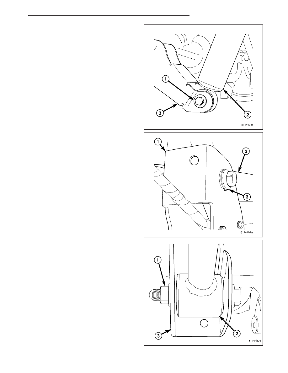
10. Remove shock absorbers (2) from axle bracket

(3).

11. Remove upper control arms (2) from axle brackets

(1).

12. Lower axle and remove coil springs and spring

isolators.

13. Remove lower control arms (2) from axle brackets

(3).

14. Lower axle and remove from vehicle.

HB

REAR AXLE - 9 1/4

3 - 115

INSTALLATION

1. Raise axle and align lower control arms. Install

control arm bolts loose at this time.

2. Install coil springs.

3. Raise axle and align upper control arms. Install

control arm bolts loose at this time.

NOTE: Bell crank bolt has a Loctite

T

patch, a new

bolt should be used. If bolt is not available, clean
bolt and apply Loctite

T

242 to the threads.

4. Install watts link bell crank bolt (2) and tighten to

217 N·m (160 ft. lbs.).

5. Install shock absorbers and tighten nuts to 102

N·m (75 ft. lbs.).

6. Install parking brake and brake components.

7. Install axle vent hose.

8. Install stabilizer bar (2) and center it with equal

spacing on both sides. Tighten bolts to 61 N·m (45
ft. lbs.).

9. Install propeller shaft (2) with reference marks (3)

aligned.

10. Install new companion flange bolts and tighten to

108 N·m (80 ft. lbs.).

NOTE: Companion flange bolts have a Loctite

T

patch, new bolts should be used. If bolts are not
available, clean bolts and apply Loctite

T

242 to the

threads.

11. With vehicle on the ground, tighten upper control

arm bolts to 170 N·m (125 ft. lbs.). Tighten lower
control arm nuts to 230 N·m (170 ft. lbs.).

3 - 116

REAR AXLE - 9 1/4

HB

ADJUSTMENTS

REAR AXLE - 9 1/4

Ring gear and pinion are supplied as matched sets.
Identifying numbers for the ring gear and pinion are
painted onto the pinion gear shaft and the side of the
ring gear. A plus + number, minus – number or zero 0
along with the gear set sequence number 01 to 99 is
on each gear. This first number (1) is the amount in
thousandths of an inch the depth varies from the stan-
dard depth setting of a pinion marked with a zero 0.
The next two numbers (2) are the sequence number
of the gear set. The standard depth provides the best
teeth contact pattern.

Compensation for pinion depth variance is achieved
with select shims (4) located behind the rear pinion
bearing (3).

PINION GEAR DEPTH VARIANCE

Original Pinion

Gear Depth

Variance

Replacement Pinion Gear Depth Variance

2

4

2

3

2

2

2

1

0

+1

+2

+3

+4

+4

+0.008

+0.007

+0.006

+0.005

+0.004

+0.003

+0.002

+0.001

0

+3

+0.007

+0.006

+0.005

+0.004

+0.003

+0.002

+0.001

0

2

0.001

+2

+0.006

+0.005

+0.004

+0.003

+0.002

+0.001

0

2

0.001

2

0.002

+1

+0.005

+0.004

+0.003

+0.002

+0.001

0

2

0.001

2

0.002

2

0.003

0

+0.004

+0.003

+0.002

+0.001

0

2

0.001

2

0.002

2

0.003

2

0.004

2

1

+0.003

+0.002

+0.001

0

2

0.001

2

0.002

2

0.003

2

0.004

2

0.005

2

2

+0.002

+0.001

0

2

0.001

2

0.002

2

0.003

2

0.004

2

0.005

2

0.006

2

3

+0.001

0

2

0.001

2

0.002

2

0.003

2

0.004

2

0.005

2

0.006

2

0.007

2

4

0

2

0.001

2

0.002

2

0.003

2

0.004

2

0.005

2

0.006

2

0.007

2

0.008

If installing a new gear, note the depth variance number of the original and replacement pinion. Add or subtract this
number from the original depth shim/oil slinger to compensate for the difference in the depth variances. The num-
bers represent thousands of an inch deviation from the standard. If the number is negative, add that value to the
required thickness of the depth shims. If the number is positive, subtract that value from the thickness of the depth
shim.

Pinion Gear Depth Variance Chart: Note where Old and New Pinion Marking columns intersect. Intersecting figure
represents plus or minus the amount needed.

HB

REAR AXLE - 9 1/4

3 - 117

PINION DEPTH MEASUREMENT

Measurements are taken with pinion bearing cups and
pinion bearings installed in the housing. Take mea-
surements with Pinion Gauge Set and Dial Indicator
C-3339 (1).

1. Assemble Pinion Height Block 6739 (1) Pinion

Block 8542 (1) and rear pinion bearing onto Screw
6741.

2. Insert assembled height gauge components, rear

bearing, and screw into the housing through pinion
bearing cups.

3. Install front pinion bearing and Cone-Nut 6740 on

screw. Tighten cone-nut on screw until Torque To
Rotate screw is 1.7 N·m (15 in. Lbs.).

4. Place Arbor Disc 8541 (1) on Arbor D-115-3 (3) in

position in the housing side bearing cradles. Install
differential bearing caps on arbor discs and tighten
cap bolts to 41 N·m (30 ft. lbs.).

3 - 118

REAR AXLE - 9 1/4

HB


Content   ..  45  46  47  48   ..