Dodge Durango (HB). Manual - part 45


  Index      Dodge     Dodge Durango (HB) - service repair manual 2005 year


Search            


Content   ..  43  44  45  46   ..


Dodge Durango (HB). Manual - part 45


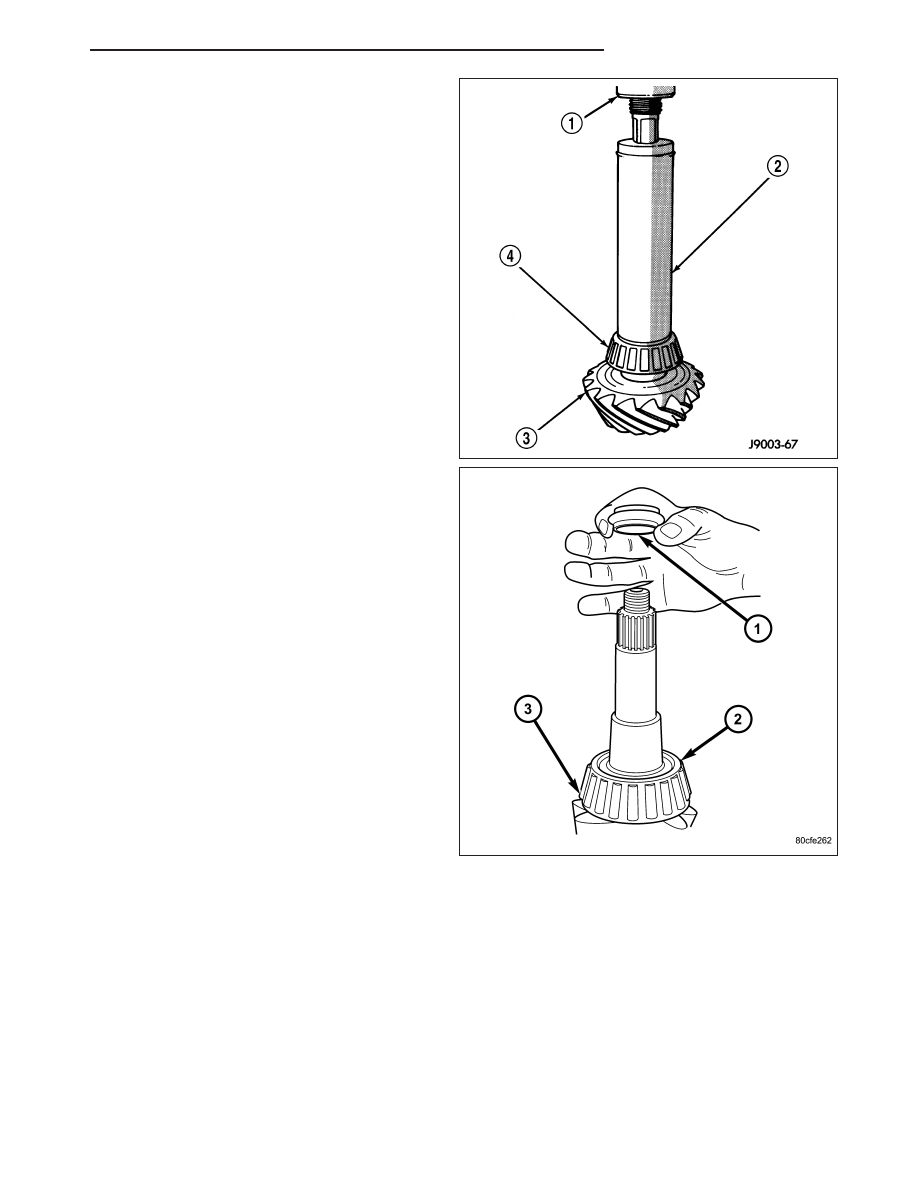
7. Install rear bearing (4) and slinger if equipped, on

pinion gear (3) with Installer 6448 (2) and a press
(1).

8. Install new collapsible spacer (1) on pinion gear

and install pinion in housing.

HB

REAR AXLE - 8 1/4

3 - 107

9. Install front pinion bearing on pinion shaft.

10. Install new pinion seal with Installer C-4076-B and

Handle C-4735-1.

11. Install pinion flange with Installer C-3718.

12. Install bolts into two of the threaded holes in the

flange 180° apart.

13. Position Holder 6719 against the flange and install

a bolt and washer into one of the remaining
threaded holes. Tighten the bolts so the Holder
6719 is held to the flange.

14. Install flange washer and a new nut on pinion and

tighten pinion nut until there is zero end-play.

15. With a torque wrench (3) tighten the pinion nut to

285 N·m (210 ft. lbs.).

CAUTION: Never loosen pinion nut to decrease
pinion bearing rotating torque and never exceed
specified preload torque. If preload torque or rotat-
ing torque is exceeded a new collapsible spacer
must be installed. Failure to follow these instruc-
tions will result in damage.

16. Slowly tighten the nut in 6.8 N·m (5 ft. lbs.) incre-

ments

until

the

desired

rotating

torque

is

achieved. Measure rotating torque frequently with
an inch pound torque wrench (2) to avoid over
crushing the collapsible spacer.

17. Check pinion rotating torque with an inch pound

torque wrench. The pinion rotating torque should
be:

Original Bearings: 1 to 3 N·m (10 to 20 in. lbs.).

New Bearings: 2 to 5 N·m (15 to 35 in. lbs.).

3 - 108

REAR AXLE - 8 1/4

HB

18. Position exciter ring on differential case. With a

brass drift slowly and evenly tap the exciter ring
into position.

19. Position ring gear on the differential case and

start two ring gear bolts. This will provide case-to-
ring gear bolt hole alignment.

20. Invert the differential case in the vise.

21. Install new ring gear bolts (2) and alternately

tighten to 102 N·m (75 ft. lbs.).

CAUTION: Never reuse the bolts that held the ring
gear to the differential case. Failure to follow these
instructions will result in fracture bolts can caus-
ing extensive damage.

22. Install differential in housing and verify gear mesh,

backlash and contact pattern.

23. Install differential cover.

HB

REAR AXLE - 8 1/4

3 - 109

REAR AXLE - 9 1/4

TABLE OF CONTENTS

page

page

REAR AXLE - 9 1/4

DIAGNOSIS AND TESTING

REAR AXLE - 9 1/4

. . . . . . . . . . . . . . . . . . . 110

REMOVAL

. . . . . . . . . . . . . . . . . . . . . . . . . . . . 114

INSTALLATION

. . . . . . . . . . . . . . . . . . . . . . . . 116

ADJUSTMENTS

REAR AXLE - 9 1/4

. . . . . . . . . . . . . . . . . . . 117

SPECIFICATIONS

REAR AXLE - 9 1/4

. . . . . . . . . . . . . . . . . . . 123

SPECIAL TOOLS

. . . . . . . . . . . . . . . . . . . . . . . 124

COVER-DIFFERENTIAL

REMOVAL

. . . . . . . . . . . . . . . . . . . . . . . . . . . . 127

INSTALLATION

. . . . . . . . . . . . . . . . . . . . . . . . 127

SHAFT-AXLE

REMOVAL

. . . . . . . . . . . . . . . . . . . . . . . . . . . . 128

INSTALLATION

. . . . . . . . . . . . . . . . . . . . . . . . 129

SEAL-AXLE SHAFT

REMOVAL

. . . . . . . . . . . . . . . . . . . . . . . . . . . . 130

INSTALLATION

. . . . . . . . . . . . . . . . . . . . . . . . 130

BEARING-AXLE

REMOVAL

. . . . . . . . . . . . . . . . . . . . . . . . . . . . 131

INSTALLATION

. . . . . . . . . . . . . . . . . . . . . . . . 132

SEAL-PINION

REMOVAL

. . . . . . . . . . . . . . . . . . . . . . . . . . . . 132

INSTALLATION

. . . . . . . . . . . . . . . . . . . . . . . . 134

DIFFERENTIAL

REMOVAL

. . . . . . . . . . . . . . . . . . . . . . . . . . . . 136

DISASSEMBLY

. . . . . . . . . . . . . . . . . . . . . . . . 137

ASSEMBLY

. . . . . . . . . . . . . . . . . . . . . . . . . . . 138

INSTALLATION

. . . . . . . . . . . . . . . . . . . . . . . . 138

BEARINGS-DIFFERENTIAL CASE

REMOVAL

. . . . . . . . . . . . . . . . . . . . . . . . . . . . 139

INSTALLATION

. . . . . . . . . . . . . . . . . . . . . . . . 140

GEAR-PINION/RING/TONE RING

REMOVAL

. . . . . . . . . . . . . . . . . . . . . . . . . . . . 140

INSTALLATION

. . . . . . . . . . . . . . . . . . . . . . . . 143

REAR AXLE - 9 1/4

DIAGNOSIS AND TESTING

REAR AXLE - 9 1/4

GEAR NOISE

Axle gear noise can be caused by insufficient lubricant, incorrect backlash, incorrect pinion depth, tooth contact,
worn/damaged gears, or the carrier housing not having the proper offset and squareness.

Gear noise usually happens at a specific speed range. The noise can also occur during a specific type of driving
condition. These conditions are acceleration, deceleration, coast, or constant load.

When road testing, first warm-up the axle fluid by driving the vehicle at least 5 miles and then accelerate the vehicle
to the speed range where the noise is the greatest. Shift out-of-gear and coast through the peak-noise range. If the
noise stops or changes greatly check for:

Insufficient lubricant.

Incorrect ring gear backlash.

Gear damage.

Differential side and pinions gears, usually do not cause noise during straight-ahead driving, when the gears are
unloaded. The side gears are loaded during turns. A worn pinion mate shaft can also cause a snapping or a knock-
ing noise.

BEARING NOISE

Bearing noise can be either a whining or a growling sound.

Pinion bearings have a constant high pitch noise, because it rotates at a faster rate. This noise changes with
vehicle speed. If noise is heard under a load, the rear pinion bearing is the source. If noise is heard during a coast,
the front pinion bearing is the source.

Differential bearings usually produce a low pitch noise. The differential bearing noise is constant and varies only
with vehicle speed.

3 - 110

REAR AXLE - 9 1/4

HB


Content   ..  43  44  45  46   ..