Dodge Durango (HB). Manual - part 29


  Index      Dodge     Dodge Durango (HB) - service repair manual 2005 year


Search            


Content   ..  27  28  29  30   ..


Dodge Durango (HB). Manual - part 29


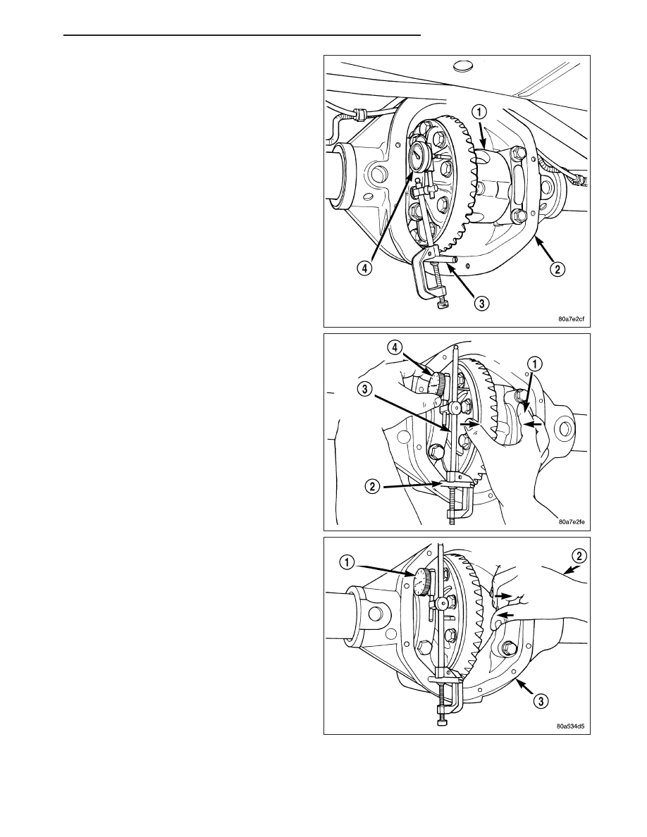
8. Thread Pilot Stud C-3288-B (3) into rear cover bolt

hole below ring gear.

9. Attach Dial Indicator C-3339 (4) to post and posi-

tion dial indicator plunger on a flat surface on a
ring gear bolt head.

10. Hold differential case firmly to pinion side (1) of

axle housing and zero dial indicator (4).

11. Hold differential case firmly (2) to the ring gear

side and record dial (1) indicator reading.

HB

FRONT AXLE - C205F

3 - 43

12. Add the dial indicator reading to the starting point

shim thicknesses to determine the total shim
thickness necessary to achieve zero differential
end play.

13. Add 0.2 mm (0.008 in) to the zero end play total.

This new total represents the thickness of shims
necessary to compress, or preload the new bear-
ings when the differential is installed.

14. Rotate dial indicator out of the way on pilot stud.

15. Remove differential case, dummy bearings, and

starting point shims from the housing.

16. Install the pinion in the axle housing. Install the

companion flange and establish the correct pinion
rotating torque.

17. Install differential case and Dummy Bearings in

axle housing with a single dummy shim on the ring gear side of the axle and tighten retaining cap bolts.

18. Position the dial indicator plunger on a flat surface between the ring gear bolt heads.

19. Push and hold differential case toward pinion.

20. Zero dial indicator face to pointer.

21. Push and hold differential case to ring gear side of the housing.

22. Record dial indicator reading.

23. Subtract 0.05 mm (0.002 in.) from the dial indicator reading to compensate for backlash between ring and pin-

ion gears. Add the resulting measurement to the thickness of the single starting point shim. This total is the
thickness of shim required to achieve proper backlash.

24. Subtract the backlash shim thickness from the total preload shim thickness. The remainder is the shim thick-

ness required on the pinion side of the axle housing.

25. Rotate dial indicator out of the way on pilot stud.

26. Remove differential case, dummy bearings and dummy shim from the housing.

27. Install new side bearing cones and cups on differential case.

28. Install Spreader W-129-B and Adapter Plates 8142-A on the housing and spread open enough to receive dif-

ferential case.

29. Place the side bearing shims in the differential housing against the housing shoulder.

30. Install the differential case in the housing.

31. Rotate the differential case several times to seat the side bearings.

32. Position the dial indicator (1) plunger against a ring gear tooth.

33. Push and hold ring gear upward while not allowing the pinion gear to rotate.

34. Zero dial indicator face to pointer.

3 - 44

FRONT AXLE - C205F

HB

35. Push and hold ring gear downward while not

allowing the pinion gear to rotate. Dial indicator
reading should be between 0.12 mm (0.005 in.)
and 0.20 mm (0.008 in.). If backlash is not within
specifications transfer the necessary amount of
shim thickness from one side of the differential
housing to the other.

36. Verify differential case and ring gear runout by

measuring ring to pinion gear backlash at eight
locations around the ring gear. Readings should
not vary more than 0.05 mm (0.002 in.). If read-
ings vary more than specified, the ring gear or the
differential case is defective.

After the proper backlash is achieved, perform the
Gear Contact Pattern procedure.

GEAR CONTACT PATTERN

Gear tooth contact pattern is used to verify the correct running position of the ring and pinion gears. This will pro-
duce low noise and long gear life. Gears which are not positioned properly may be noisy and have shorten gear life.

1. Wipe clean each tooth of the ring gear.

2. Apply gear marking compound to all of the ring gear teeth.

3. Verify bearing cap bolts are torque specification.

4. Apply parking brakes lightly to create at 14 N·m (10 ft. lbs.) pinion rotating torque.

5. Rotate the pinion/pinion yoke 4 full revolutions in each directions.

6. Read gear tooth contact pattern.

Gear contact pattern is correct. Backlash and pinion
depth is correct.

HB

FRONT AXLE - C205F

3 - 45

Ring gear is too far away from the pinion gear, coats
side toe (1) drive side heel (2). Decrease backlash by
moving ring gear closer to the pinion gear using the
adjusters.

Ring gear is too close to the pinion gear, drive side
toe (1) coast side heel (2). Increase backlash by mov-
ing ring gear away from the pinion gear using the
adjusters.

Ring gear is too far away from the pinion gear drive
side heel (1) coast side heel (2). Decrease backlash
by moving ring gear closer to the pinion gear using
the adjusters.

Ring gear is too close to the pinion gear, drive side
toe (1) coast side toe (2). Increase backlash, by mov-
ing ring gear away from the pinion gear using the
adjusters.

3 - 46

FRONT AXLE - C205F

HB


Content   ..  27  28  29  30   ..