Dodge Dakota (R1). Manual - part 862
Symptom:
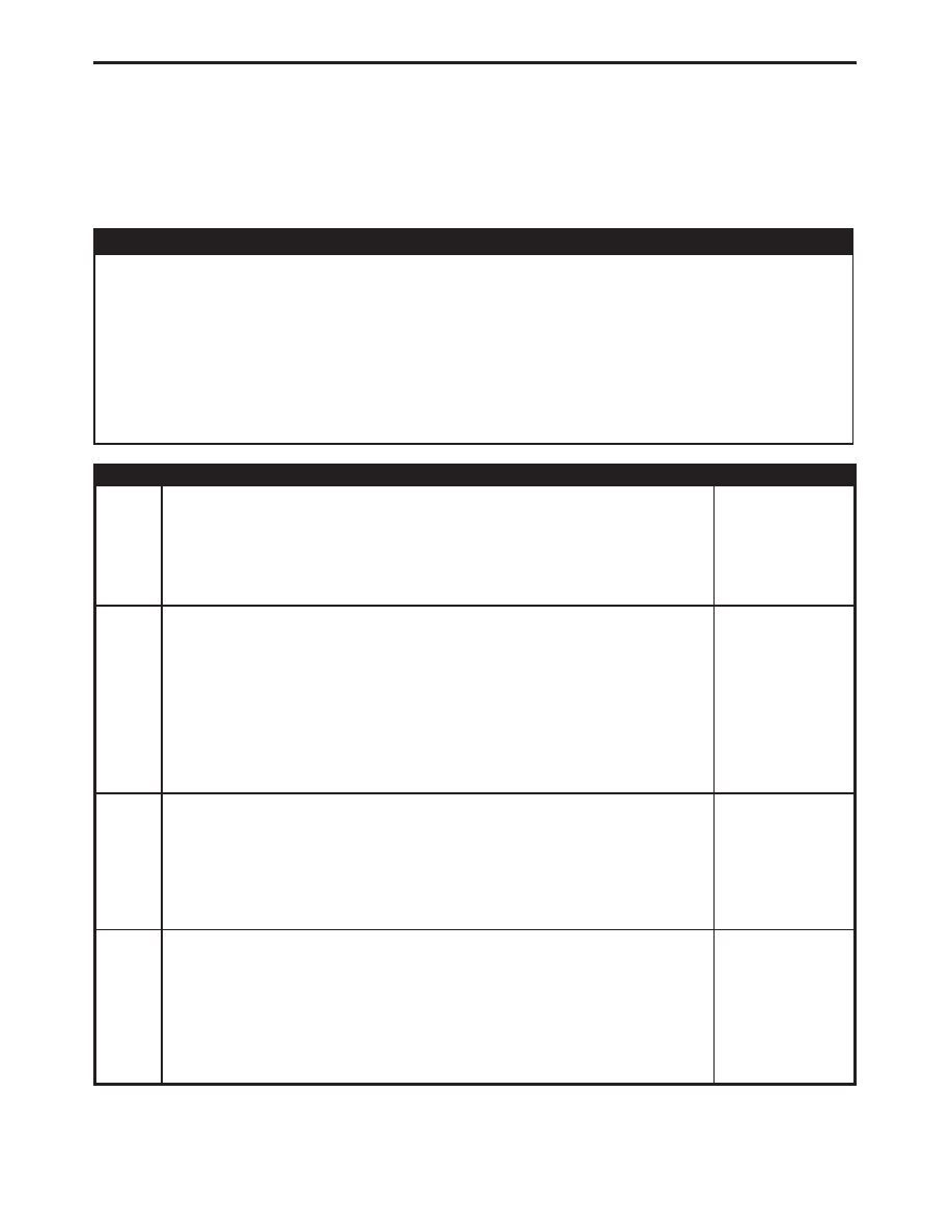
P1491-RAD FAN CONTROL RELAY CIRCUIT
POSSIBLE CAUSES
RADIATOR FAN CONTROL RELAY CIRCUIT WIRE HARNESS INTERMITTENT PROBLEM
RADIATOR FAN CONTROL RELAY CIRCUIT WIRE HARNESS OBSERVABLE PROBLEM
RADIATOR FAN RELAY GROUND CIRCUIT OPEN
RAD FAN RELAY CONTROL CIRCUIT OPEN
RADIATOR FAN RELAY CONTROL CIRCUIT SHORT TO GROUND
RADIATOR FAN CONTROL RELAY
PCM
TEST
ACTION
APPLICABILITY
1
Turn the ignition on.
With the DRBIII
t, actuate the Radiator Fan Relay.
Does the Radiator Fan Motor Cycle on and off?
All
Yes
→
No
→
2
Turn the ignition on.
With the DRBIII
t, actuate the Radiator Fan Relay.
Wiggle the wiring harness from the Radiator Fan Relay connector to the PCM
harness connector.
Did the wiggling interrupt the Radiator Fan Motor cycling?
All
Yes
→
Repair as necessary where wiggling caused the cycling to be
interrupted.
Perform POWERTRAIN VERIFICATION TEST VER - 2.
No
→
3
Turn the ignition off.
Using the schematic as a guide, inspect the wiring and connectors.
Were any problems found?
All
Yes
→
Repair as necessary.
Perform POWERTRAIN VERIFICATION TEST VER - 2.
No
→
Test Complete.
4
Turn the ignition off.
Remove the Radiator Fan Relay form the PDC.
Measure the Radiator Fan Relay Ground Circuit to Ground.
Is the resistance below 5.0 ohms?
All
Yes
→
No
→
Repair the open Ground Circuit.
Perform POWERTRAIN VERIFICATION TEST VER - 2.
180
DRIVEABILITY - GAS