Dodge Dakota (R1). Manual - part 799


  Index      Dodge     Dodge Dakota (R1) - service repair manual 2000 year


Search            


Content   ..  797  798  799  800   ..


Dodge Dakota (R1). Manual - part 799


(4) If the vehicle is so equipped, remove the nuts

that secure the vehicle speed control servo mounting
bracket to the studs on the cowl plenum panel and
move the servo far enough to access the accumulator
refrigerant line couplers (Refer to 8 - ELECTRICAL/
SPEED CONTROL/SERVO - REMOVAL).

(5) Loosen the screw that secures the accumulator

retaining band to the support bracket on the dash
panel.

(6) Disconnect the suction line refrigerant line fas-

tener from the accumulator. Install plugs in, or tape
over all of the opened refrigerant line fittings.

(7) Disconnect the accumulator inlet tube refriger-

ant line secondary clip from the accumulator. Install
plugs in, or tape over all of the opened refrigerant
line fittings.

(8) Pull the accumulator and retaining band unit

forward until the screw in the band is clear of the
slotted hole in the support bracket on the dash panel.

(9) Remove the accumulator from the vehicle.

INSTALLATION

WARNING: (Refer to 24 - HEATING & AIR CONDI-
TIONING/PLUMBING - WARNING) AND (Refer to 24 -
HEATING & AIR CONDITIONING/PLUMBING - CAU-
TION) BEFORE PERFORMING THE FOLLOWING
OPERATION.

(1) Install the accumulator and retaining band as

a unit by sliding the screw in the band into the slot-
ted hole in the support bracket on the dash panel.

(2) Remove the tape or plugs from the refrigerant

line fittings on the accumulator inlet tube and the
evaporator outlet tube. Connect both refrigerant lines
to the accumulator. Tighten the fasteners to 25.99
±3.39 N·m (230 ±30 in. lbs.).

(3) Tighten the accumulator retaining band screw

to 4.5 N·m (40 in. lbs.).

(4) Plug the wire harness connector into the low

pressure cycling clutch switch.

(5) Connect the battery negative cable.
(6) Evacuate the refrigerant system. See Refriger-

ant System Evacuate in the Service Procedures sec-
tion of this group.

(7) Charge the refrigerant system. See Refrigerant

System Charge in the Service Procedures section of
this group.

NOTE: If the accumulator is replaced, add 120 mil-
liliters (4 fluid ounces) of refrigerant oil to the
refrigerant system. Use only refrigerant oil of the
type recommended for the compressor in the vehi-
cle.

HEATER CORE

DESCRIPTION

The heater core is located in the HVAC housing,

under the instrument panel. It is a heat exchanger
made of rows of tubes and fins.

The heater core is not repairable and if damaged it

must be replaced.

OPERATION

Engine coolant is circulated through heater hoses

to the heater core at all times. As the coolant flows
through the heater core, heat removed from the
engine is transferred to the heater core fins and
tubes. Air directed through the heater core picks up
the heat from the heater core fins. The blend door

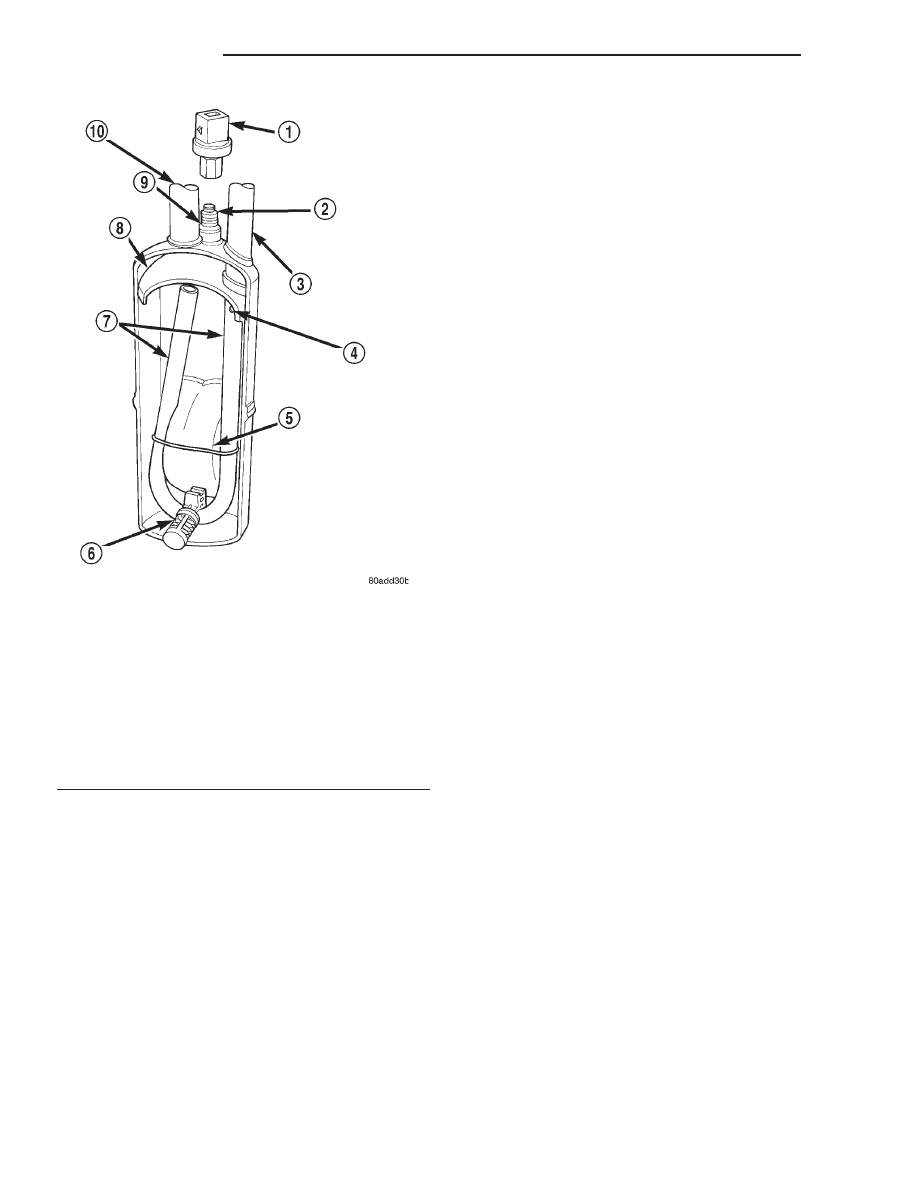
Fig. 6 ACCUMULATOR - TYPICAL

1 - A/C LOSS OF CHARGE SWITCH
2 - LOSS OF CHARGE SWITCH FITTING
3 - OUTLET TO COMPRESSOR
4 - ANTI-SIPHON HOLE
5 - DESICCANT BAG
6 - OIL RETURN ORIFICE FILTER
7 - VAPOR RETURN TUBE
8 - ACCUMULATOR DOME
9 - O-RING SEAL
10 - INLET FROM EVAPORATOR

24 - 42

PLUMBING

AN

ACCUMULATOR (Continued)

allows control of the heater output air temperature
by controlling how much of the air flowing through
the HVAC housing is directed through the heater
core. The blower motor speed controls the volume of
air flowing through the HVAC housing.

The heater core cannot be repaired and, if faulty or

damaged, it must be replaced.

REMOVAL

WARNING: ON VEHICLES EQUIPPED WITH AIR-
BAGS, DISABLE THE AIRBAG SYSTEM BEFORE
ATTEMPTING ANY STEERING WHEEL, STEERING
COLUMN, OR INSTRUMENT PANEL COMPONENT
DIAGNOSIS OR SERVICE. DISCONNECT AND ISO-
LATE THE BATTERY NEGATIVE (GROUND) CABLE,
THEN WAIT TWO MINUTES FOR THE AIRBAG SYS-
TEM CAPACITOR TO DISCHARGE BEFORE PER-
FORMING

FURTHER

DIAGNOSIS

OR

SERVICE.

FAILURE TO TAKE THE PROPER PRECAUTIONS
COULD RESULT IN ACCIDENTAL AIRBAG DEPLOY-
MENT AND POSSIBLE PERSONAL INJURY.

(1) Remove the passenger side rear trim panel

(Refer to 23 - BODY/INTERIOR/QUARTER PANEL
TRIM - REMOVAL).

(2) Drain to cooling systems (Refer to 7 - COOL-

ING - STANDARD PROCEDURE) or (Refer to 7 -
COOLING - STANDARD PROCEDURE).

(3) Remove the three blend door actuator screws.
(4) Remove the blend door actuator and place

aside.

(5) Remove the two screws from the heater/evapo-

rator tubes plastic retainer.

(6) Using spring clamp type pliers remove the

clamps from the heater hoses,

(7) Using a twisting motion remove the heater

hoses from the heater core.

(8) Lift the heater core out of the heater-A/C hous-

ing.

INSTALLATION

(1) Insert the heater core into the bottom of the

heater-A/C housing.

(2) Using a twisting motion install the heater

hoses to the heater core.

(3) Using spring clamp type pliers install the

clamps to the heater hoses.

(4) Install the two screws to the heater/evaporator

tubes plastic retainer.

(5) Install blend door actuator.
(6) Install the three blend door actuator screws.
(7) Refill the cooling system (Refer to 7 - COOL-

ING - STANDARD PROCEDURE) or (Refer to 7 -
COOLING - STANDARD PROCEDURE).

(8) Install the passenger side rear trim panel

(Refer to 23 - BODY/INTERIOR/QUARTER PANEL
TRIM - INSTALLATION).

LIQUID LINE

REMOVAL

Any kinks or sharp bends in the refrigerant plumb-

ing will reduce the capacity of the entire air condi-
tioning system. Kinks and sharp bends reduce the
flow of refrigerant in the system. High pressures are
produced in the refrigerant system when the air con-
ditioning compressor is operating. Extreme care must
be exercised to make sure that each of the refriger-
ant system connections is pressure-tight and leak
free.

WARNING: (Refer to 24 - HEATING & AIR CONDI-
TIONING/PLUMBING - WARNING) AND (Refer to 24 -
HEATING & AIR CONDITIONING/PLUMBING - CAU-
TION) BEFORE PERFORMING THE FOLLOWING
OPERATION.

(1) Disconnect and isolate the battery negative

cable.

(2) Recover the refrigerant from the refrigerant

system (Refer to 24 - HEATING & AIR CONDITION-
ING/PLUMBING/REFRIGERANT

-

STANDARD

PROCEDURE).

(3) Remove the engine air filter housing (Refer to 9

- ENGINE/AIR INTAKE SYSTEM/AIR CLEANER
ELEMENT - REMOVAL).

(4) If the vehicle is so equipped, remove the nuts

that secure the vehicle speed control servo mounting
bracket to the studs on the cowl plenum panel and
move the servo far enough to access the liquid line to
evaporator coupler (Refer to 8 - ELECTRICAL/
SPEED CONTROL/SERVO - REMOVAL).

(5) Disconnect the liquid line fastener at the con-

denser, and refrigerant line coupler at the evaporator
(Refer to 24 - HEATING & AIR CONDITIONING/
PLUMBING - REMOVAL).

(6) Disengage the two clips that secure the liquid

line to the inner fender shield.

(7) Remove the liquid line from the vehicle.

INSTALLATION

High pressures are produced in the refrigerant sys-

tem when the air conditioning compressor is operat-
ing. Extreme care must be exercised to make sure
that each of the refrigerant system connections is
pressure-tight and leak free.

AN

PLUMBING

24 - 43

HEATER CORE (Continued)

WARNING: (Refer to 24 - HEATING & AIR CONDI-
TIONING/PLUMBING - WARNING) AND (Refer to 24 -
HEATING & AIR CONDITIONING/PLUMBING - CAU-
TION) BEFORE PERFORMING THE FOLLOWING
OPERATION.

(1) Install the liquid line in the two clips on the

inner fender shield.

(2) Remove the tape or plugs from the refrigerant

line fittings on the liquid line, the condenser outlet,
and the evaporator inlet. Connect the liquid line to
the condenser and the evaporator and install the sec-
ondary clip (Refer to 24 - HEATING & AIR CONDI-
TIONING/PLUMBING - INSTALLATION). Tighten
the fastener at the condenser to 22.6 ±3.38 N·m (200
±30 in. lbs.).

(3) If the vehicle is so equipped, reinstall the vehi-

cle speed control servo mounting bracket to the studs
on the cowl plenum panel (Refer to 8 - ELECTRI-
CAL/SPEED CONTROL/SERVO - INSTALLATION).

(4) Reinstall the engine air filter housing (Refer to

9 - ENGINE/AIR INTAKE SYSTEM/AIR CLEANER
ELEMENT - INSTALLATION).

(5) Connect the battery negative cable.
(6) Evacuate the refrigerant system (Refer to 24 -

HEATING & AIR CONDITIONING/PLUMBING/RE-
FRIGERANT - STANDARD PROCEDURE).

(7) Charge the refrigerant system (Refer to 24 -

HEATING & AIR CONDITIONING/PLUMBING/RE-
FRIGERANT - STANDARD PROCEDURE).

REFRIGERANT

DESCRIPTION

The refrigerant used in this air conditioning sys-

tem is a HydroFluoroCarbon (HFC), type R-134a.
Unlike R-12, which is a ChloroFluoroCarbon (CFC),
R-134a refrigerant does not contain ozone-depleting
chlorine. R-134a refrigerant is a non-toxic, non-flam-
mable, clear, and colorless liquefied gas.

Even though R-134a does not contain chlorine, it

must be reclaimed and recycled just like CFC-type
refrigerants. This is because R-134a is a greenhouse
gas and can contribute to global warming.

OPERATION

R-134a refrigerant is not compatible with R-12

refrigerant in an air conditioning system. Even a
small amount of R-12 added to an R-134a refrigerant
system will cause compressor failure, refrigerant oil
sludge or poor air conditioning system performance.
In addition, the PolyAlkylene Glycol (PAG) synthetic
refrigerant oils used in an R-134a refrigerant system
are not compatible with the mineral-based refriger-
ant oils used in an R-12 refrigerant system.

R-134a refrigerant system service ports, service

tool couplers and refrigerant dispensing bottles have
all been designed with unique fittings to ensure that
an R-134a system is not accidentally contaminated
with the wrong refrigerant (R-12). There are also
labels posted in the engine compartment of the vehi-
cle and on the compressor identifying to service tech-
nicians that the air conditioning system is equipped
with R-134a.

DIAGNOSIS AND TESTING- REFRIGERANT
SYSTEM LEAKS

WARNING: REVIEW THE WARNINGS AND CAU-
TIONS IN THE GENERAL INFORMATION SECTION
NEAR THE FRONT OF THIS GROUP BEFORE LEAK
TESTING THE SYSTEM.

If the air conditioning system does not cool prop-

erly, the A/C system performance should be tested.
See A/C Performance in the Diagnosis and Testing
section of this group for the procedures. If the A/C
system refrigerant fill is found to be low or if the sys-
tem is empty; a leak at a refrigerant line, connector
fitting, component, or component seal is likely.

An electronic leak detector designed for R-134a

refrigerant, or a fluorescent R-134a leak detection
dye and a black light are recommended for locating
and confirming refrigerant system leaks. Refer to the
operating instructions supplied by the equipment
manufacturer for the proper care and use of this
equipment.

An oily residue on or near refrigerant system lines,

connector fittings, components, or component seals
can indicate the general location of a possible refrig-
erant leak. However, the exact leak location should
be confirmed with an electronic leak detector prior to
component repair or replacement.

To detect a leak in the refrigerant system with an

electronic leak detector, perform one of the following
procedures:

SYSTEM EMPTY

(1) Evacuate the refrigerant system (Refer to 24 -

HEATING & AIR CONDITIONING/PLUMBING/RE-
FRIGERANT - STANDARD PROCEDURE).

(2) Connect and dispense 0.283 kilograms (0.625

pounds or 10 ounces) of R-134a refrigerant into the
evacuated refrigerant system (Refer to 24 - HEAT-
ING & AIR CONDITIONING/PLUMBING/REFRIG-
ERANT - STANDARD PROCEDURE).

(3) Position the vehicle in a wind-free work area.

This will aid in detecting small leaks.

(4) With the engine not running, use a electronic

R-134a leak detector and search for leaks. Because
R-134a refrigerant is heavier than air, the leak detec-

24 - 44

PLUMBING

AN

LIQUID LINE (Continued)

tor probe should be moved slowly along the bottom
side of all refrigerant lines, connector fittings and
components.

(5) To inspect the evaporator coil for leaks, insert

the electronic leak detector probe into the center
instrument panel outlet and the floor duct outlet. Set
the blower motor switch to the lowest speed position,
and the mode control switch in the recirculation
mode (Max-A/C).

SYSTEM LOW

(1) Position the vehicle in a wind-free work area.

This will aid in detecting small leaks.

(2) Bring the refrigerant system up to operating

temperature and pressure. This is done by allowing
the engine to run with the air conditioning system
turned on for five minutes.

(3) With the engine not running, use a electronic

R-134a leak detector and search for leaks. Because
R-134a refrigerant is heavier than air, the leak detec-
tor probe should be moved slowly along the bottom
side of all refrigerant lines, connector fittings and
components.

(4) To inspect the evaporator coil for leaks, insert

the electronic leak detector probe into the center
instrument panel outlet and the floor duct outlet. Set
the blower motor switch to the lowest speed position,
and the mode control switch in the recirculation
mode (Max-A/C).

STANDARD PROCEDURE - REFRIGERANT
SYSTEM EVACUATE

WARNING: (Refer to 24 - HEATING & AIR CONDI-
TIONING/PLUMBING - WARNING) AND (Refer to 24 -
HEATING & AIR CONDITIONING/PLUMBING - CAU-
TION) BEFORE PERFORMING THE FOLLOWING
OPERATION.

If the refrigerant system has been open to the

atmosphere, it must be evacuated before the system
can be charged. If moisture and air enters the system
and becomes mixed with the refrigerant, the com-
pressor head pressure will rise above acceptable
operating levels. This will reduce the performance of
the air conditioner and damage the compressor.
Evacuating the refrigerant system will remove the
air and boil the moisture out of the system at near
room temperature. To evacuate the refrigerant sys-
tem, use the following procedure:

(1) Connect a R-134a refrigerant recovery/recy-

cling/charging station that meets SAE Standard
J2210 and a manifold gauge set to the refrigerant
system of the vehicle.

(2) Open the low and high side valves and start

the charging station vacuum pump. When the suc-

tion gauge reads 88 kPa (26 in. Hg.) vacuum or
greater, close all of the valves and turn off the vac-
uum pump.

(a) If the refrigerant system fails to reach the

specified vacuum, the system has a leak that must
be corrected. See Refrigerant System Leaks in the
Diagnosis and Testing section of this group for the
procedures.

(b) If the refrigerant system maintains the spec-

ified vacuum for five minutes, restart the vacuum
pump, open the suction and discharge valves and
evacuate the system for an additional ten minutes.
(3) Close all of the valves, and turn off the charg-

ing station vacuum pump.

(4) The refrigerant system is now ready to be

charged with R-134a refrigerant. See Refrigerant
System Charge in the Service Procedures section of
this group.

STANDARD PROCEDURE- REFRIGERANT
RECOVERY

WARNING: (Refer to 24 - HEATING & AIR CONDI-
TIONING/PLUMBING - WARNING) AND (Refer to 24 -
HEATING & AIR CONDITIONING/PLUMBING - CAU-
TION) BEFORE PERFORMING THE FOLLOWING
OPERATION.

A R-134a refrigerant recovery/recycling/charging

station that meets SAE Standard J2210 must be
used to recover the refrigerant from an R-134a refrig-
erant system. Refer to the operating instructions sup-
plied by the equipment manufacturer for the proper
care and use of this equipment.

STANDARD PROCEDURE- REFRIGERANT
SYSTEM CHARGE

WARNING: (Refer to 24 - HEATING & AIR CONDI-
TIONING/PLUMBING - WARNING) AND (Refer to 24 -
HEATING & AIR CONDITIONING/PLUMBING - CAU-
TION) BEFORE PERFORMING THE FOLLOWING
OPERATION.

After the refrigerant system has been tested for

leaks and evacuated, a refrigerant charge can be
injected into the system. See Refrigerant Charge
Capacity in the Service Procedures section of this
group for the proper amount of the refrigerant
charge.

A R-134a refrigerant recovery/recycling/charging

station that meets SAE Standard J2210 must be
used to charge the refrigerant system with R-134a
refrigerant. Refer to the operating instructions sup-
plied by the equipment manufacturer for the proper
care and use of this equipment.

AN

PLUMBING

24 - 45

REFRIGERANT (Continued)


Content   ..  797  798  799  800   ..