Dodge Dakota (R1). Manual - part 784


  Index      Dodge     Dodge Dakota (R1) - service repair manual 2000 year


Search            


Content   ..  782  783  784  785   ..


Dodge Dakota (R1). Manual - part 784


(4) Align the left upper hinge bracket cover and

install the bolt.

(5) Install the hinge pivot bolt. Tighten the bolt to

24 N·m (17 ft. lbs.) torque.

CENTER SEAT ARMREST /
CONSOLE

REMOVAL - CENTER SEAT/CONSOLE

(1) Remove bucket seats
(2) Remove the bolts attaching the center seat to

the bucket seat inboard seat tracks (Fig. 3).

(3) Route the seat belt buckles through the elastic

retaining straps.

(4) Separate the center seat/console from the

bucket seats.

REMOVAL - CENTER ARMREST/CONSOLE
LATCH

(1) Place the armrest/console in the down position.
(2) Open the armrest/console lid and remove the

two screws attaching the latch bezel cover and
remove the latch cover bezel and the latch button
(Fig. 4).

(3) Using a drill stop, and protecting the surround-

ing trim and upholstery, drill the heads off the two
rivets holding the latch to the armrest/console. Do
not penetrate the latch bracket.

(4) Remove the latch assembly.
(5) Using the correct size drill bit, remove the

remaining portion of the rivet.

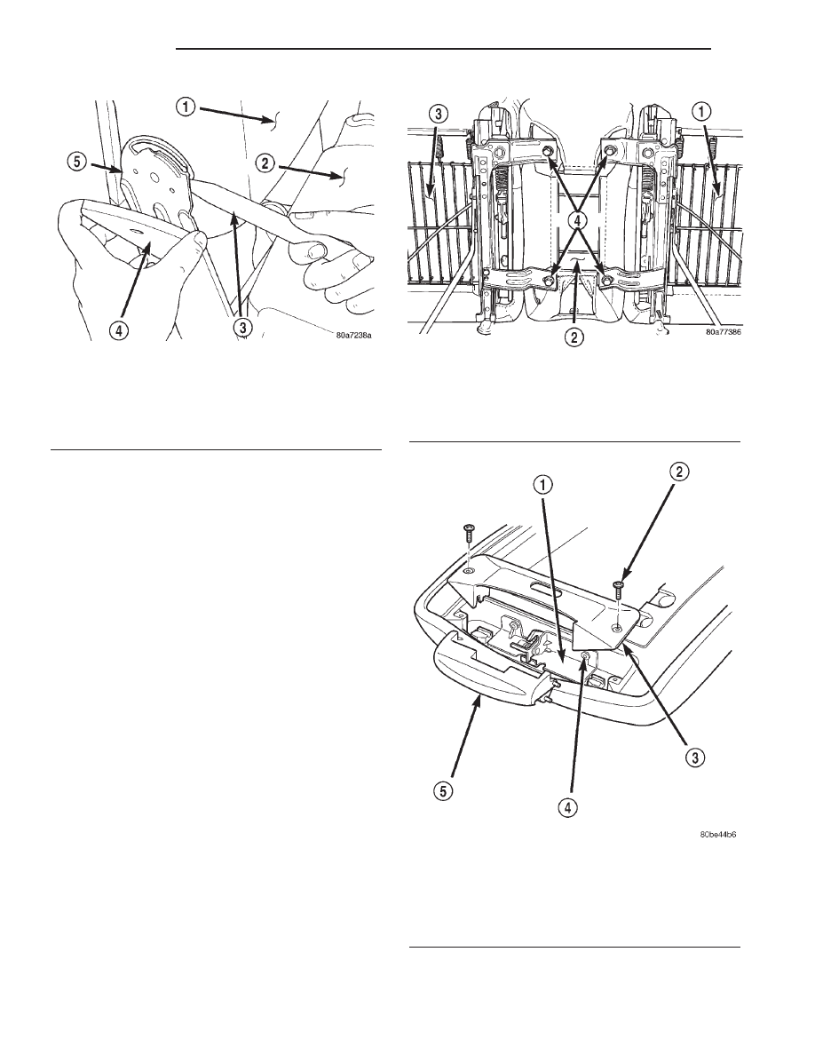
Fig. 2 Pivot Bracket

1 - SEAT BACK
2 - CUSHION
3 - TRIM STICK
4 - COVER
5 - PIVOT BRACKET

Fig. 3 Center Seat/Console

1 - PASSENGER SEAT
2 - CENTER SEAT/CONSOLE
3 - DRIVERS SEAT
4 - BOLTS

Fig. 4 Center Armrest/Console

1 - LATCH ASSEMBLY
2 - SCREW
3 - LATCH COVER BEZEL
4 - RIVET
5 - BUTTON

23 - 124

SEATS

AN

CENTER CONSOLE LID (Continued)

REMOVAL - CENTER ARMREST UPPER
INERTIA LATCH COVER

(1) Move the drivers seat position to full forward

with seat back full forward.

(2) Place center arm rest in the down position.
(3) Remove the screw securing the cover to the

inertia latch (Fig. 5).

(4) Remove the upper and lower inertia latch cov-

ers.

INSTALLATION - CENTER SEAT/CONSOLE

(1) Position the center seat/console onto the bucket

seat inboard seat tracks.

(2) Route the seat belt buckles through the elastic

retaining straps.

(3) Install the bolts attaching the center seat to

the bucket seat inboard tracks. Tighten the bolts to
24 N·m (17 ft. lbs.) torque.

(4) Install bucket seats

INSTALLATION - CENTER ARMREST/COSOLE
LATCH

(1) Before installing the latch assembly, clean the

area of any debris.

(2) Align the latch with the hole openings in the

bin.

(3) Secure the latch assembly with new rivets.
(4) Place the button in position and retain with

the latch cover bezel.

(5) Attach the latch cover bezel with the screws.
(6) Inspect the latch assembly by cycling through a

full range of lid motions.

INSTALLATION - CENTER ARMREST UPPER
INERTIA LATCH COVER

(1) Install the upper latch cover onto the upper

latch inertia arm. Ensure the check strap loops
under the stud on the side of the lower stanchion/
post.

(2) Install the lower latch cover onto the inertia

latch upper arm working it around the latch bracket.

(3) Align the lower latch cover, the upper latch

cover, and the latch bracket to the screw hole on the
arm.

(4) Secure the cover with the screw and tighten to

4.15 N·m (37 in. lbs.).

(5) Cycle the armrest through a full range of travel

and check for freedom of movement. Adjust the latch
covers as necessary.

CENTER SEAT CUSHION
COVER

REMOVAL

(1) Remove the bucket seats.
(2) Separate the center seat from the bucket seats.
(3) Remove the seat back/console lid.
(4) Disengage the J-straps from the cushion frame

(Fig. 6).

(5) Separate the cushion/cover from the frame.

INSTALLATION

(1) Position the cushion/cover on the frame.
(2) Engage the J-straps from the cushion frame.
(3) Install the seat back/console lid.
(4) Attach the center seat to the bucket seats.
(5) Install the bucket seats.

Fig. 5 Armrest/Console Inertia Latch Hinge Cover

1 - SEAT CUSHION
2 - SEAT BACK/CONSOLE LID
3 - HINGE COVER

Fig. 6 Center Seat Cushion/Cover

1 - J-STRAPS
2 - CENTER SEAT CUSHION COVER

AN

SEATS

23 - 125

CENTER SEAT ARMREST / CONSOLE (Continued)

SEAT

REMOVAL - BENCH SEAT

(1) Move seat to full forward position.
(2) Remove bolts attaching seat track to floor pan.
(3) Move seat to full rearward position.
(4) Remove bolts attaching seat track to floor pan

(Fig. 7).

(5) Tilt setback forward and lift seat out through

door.

NOTE: Do not activate seat track adjusters once
bolts are removed.

REMOVAL - BUCKET SEAT

(1) If equipped, remove side shield and disengage

power seat switch connector.

If the vehicle is equipped with a 40/20/40 seat,

remove bucket seats and console as one assembly
(Fig. 8).

(2) Move seat to full forward position.
(3) Remove rear screws attaching trim cover to

seat track (Fig. 9).

(4) Remove rear bolts attaching rear seat track to

floor pan.

(5) Move seat to full rearward position.
(6) Remove front screws attaching trim cover to

seat track (Fig. 9).

(7) Remove front bolts attaching front seat track to

floor pan.

NOTE: Do not actuate recliner or track adjuster
once bolts are removed.

(8) Tilt setback forward and lift seat out through

door.

REMOVAL - REAR SEAT QUAD CAB

The quad cab rear seat is a 60/40 seat. Each seat is

serviceable separately.

(1) Fold the seating cushion up.
(2) Remove the fasteners retaining the seat to the

cab floor.

Fig. 7 Bench Seat

1 - U-NUT
2 - BENCH SEAT
3 - CUP HOLDER

Fig. 8 40/20/40/ Front Seat

1 - 40/20/40 FRONT SEAT
2 - U—NUT
3 - TRIM COVER

Fig. 9 Bucket Seat & Seat Track Trim Cover

1 - TRIM COVER
2 - BUCKET SEAT
3 - U-NUT

23 - 126

SEATS

AN

(3) Lift the seat assembly off the retaining studs

and the cab back hooks (Fig. 10).

(4) Feed the seat belt between the seat cushion

and seat back.

(5) Remove the seat through the rear door.

INSTALLATION - BENCH SEAT

(1) Position seat in vehicle.

NOTE: Ensure each seat track is equally positioned
in the full rearward position.

(2) Install the front bolts attaching seat track to

floor pan. Tighten bolts to 28 N·m (20 ft. lbs.) torque.

(3) Move seat to full forward position.
(4) Install rear bolts attaching seat track to floor

pan. Tighten bolts to 40 N·m (30 ft. lbs.) torque.

INSTALLATION - BUCKET SEAT

(1) Position seat in vehicle.

NOTE: Ensure each seat track is equally positioned
in the full rearward position.

(2) Install bolts attaching front seat track to floor

pan. Tighten to 28 N·m (20 ft. lbs.) torque.

(3) Install front screws attaching trim cover to seat

track.

(4) Move seat to full forward position.
(5) Install bolts attaching rear inboard seat track

to floor pan. Tighten to 40 N·m (30 ft. lbs.) torque.

(6) Install bolts attaching rear outboard seat track

to floor pan. Tighten to 28 N·m (20 ft. lbs.) torque.

(7) Install rear screws attaching trim cover to seat

track.

(8) If equipped, engage power seat switch connec-

tor and install side shield.

INSTALLATION - REAR SEAT QUAD CAB

(1) Position the seat on the cab back hooks and the

floor studs.

(2) Feed the seat belt between the seat cushion

and the seat back.

(3) Ensure the seat back is firmly hooked to the

cab back retainers.

(4) Tighten the cab floor fasteners.

Fig. 10 Rear Seat Quad Cab

1 - HOOK
2 - RETAINER
3 - CAB BACK

4 - SEAT BRACKET
5 - CAB FLOOR STUD

AN

SEATS

23 - 127

SEAT (Continued)


Content   ..  782  783  784  785   ..